You already help me in the passed and i just want to say thank to always be ready to help newbies like me:)
Your idea is to connect the Leds in parallels? do you think the voltage will increase a lot?
I am also able to use a relay shield with 10A, i have two of them. One the red Leds and other one for the UV Leds.
I have been thinking a little about this project and i decide to change a little:
Only one side with 100 UV Leds, for the PCB with two side i will do the job in two step
i think 50 Red Led it´s enough, it´s just to help the alignment of PCB and transparency paper in a dark room.
i will use a switch to cut off the UV Light in case of opening the box in service.
No, wire the LEDs in series.
Say you had a 25V source, and each LED had Vf of 2V.
Then wire:
25V-anode1, cathode1 to anode2, cathode 2 to anode3, ... cathode 12 to resistor, resistor to transistor collector, emitter to Gnd. High on base turns it on, low on base turns it off. Simple 2n2222A NPN transistor with 20mA into its base will do it.
Wire 8 strings like that, all between 25V and transistor collector. 96 LEDs.
20mA each string, 160mA total.
(25V - (12 x 2V) - 0.7V)/.02A = 15 ohm resistor
Do the math for the voltage sourcc you have, Vf of your LEDs, Vce of the transistor you use.
the Vf for the Led im to buy are between 3.0V and 3.4V, i use 3.4V
0.7V for transistor
20mA for each Led
With this i have a resistor of 145ohm but i only can use 6 leds in each string
I see arduino Uno can handle with 40mA in I/O Pin, if i have the 20ma into the base of 2n2222A i can use two strings for each Output of my Arduino Uno.
For 96 Leds i will need 16 String and 8 Output in my arduino, i can use the others output for my Red Leds.
What do you think?
if i can increase the power supply i will be able to put more Leds in each string and also decrease the ports i will need in arduino board, i am right?
You can use a different transistor now that you know how much current.
16 .02 = 320mA.
Use a N-channel MOSFET.
On-resistance is .039ohm
With .32A flowing thru it, it will have V=IR = .012V across it, so you could with 7 LEDs in a string,
MOSFETs are voltage controlled, very little current, so Arduino can drive 1 via 220 resistor, and the MOSFET can do all 16 strings and only dissipate 4mW of power.
(24 - (73.4) - .012)/.02 = 10 ohm resistor
Hi CrossRoads,
I will use the Transistor, i have on at home.
I have one doubt +, i understand the part in the transistor is working like a switch but i don´t really understand the calculation, can you explain a little bit or a link with explanation?
I see a fee tutorials in internet where there are using one resistor in the base of the transistor, do you think i will needed?
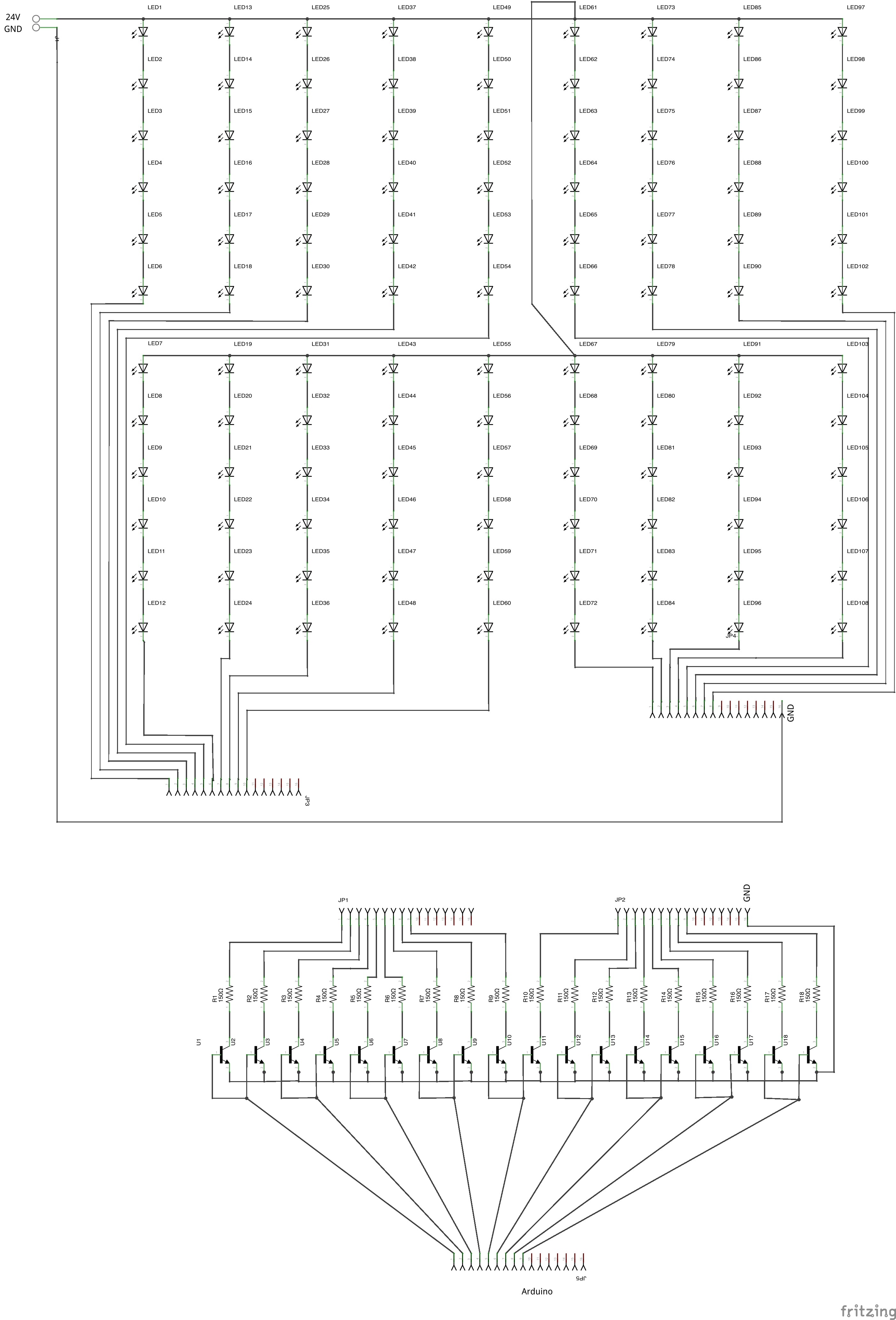
I take your advice and finally i finishing the circuit in fritzing, i don´t have any experience in PCB design but i´m starting some video tutorials for Eagle software.
Can you take a look please, i´m a little worried about the current in the lines GND and 24V, maybe i need to put this lines bigger...
I see a few switch transistors circuits in internet and all of them have a resistor between the base of the transistor and the arduino, do you think i will needed?
I make the PCB design in two circuit, one for the Leds and the other one for the resistances and transistores (the second one have two layers), in the first stage i will dismiss the red Leds.
Schematic is huge, next time resize to 1000 wide.
Transistor is needed between arduino and NPN base to limit arduino current output.
Base of transistor looks like a diode to gnd, voltage is named Vbe. Usually 0.3, 0.5, 0.7V somewhere in that range. Current from arduino should be <20mA, so resistor value of (5V - 0.5)/.02A = 225 or more should be used.
You don't need so many transistors - several LED strings can be controlled from 1 transistor - maybe all of them depending on the Max continuous current rating from collector to emitter of the transistor.
I will use the P2N2222A Transistor, based in what you told me:
In the data sheet of P2N2222A i see the Base?Emitter Saturation min Voltage Vbe is 0.6V, so (5-0.6)/.02=220, i will use a 220ohm resistor between arduino output and the base of each transistor.
This transistor can handle with 600mA between C and E, for 20mA for each Leds, 6 Leds in each string give me the same 20mA because they are in serie in the string, i have 18 string it will be 20mA*18=360mA so i can use only 1 transistor. i will the use 3 transistor to divide better the circuit and also i can drive the 3 parts of Leds separately in the arduino.