74HC595 Shift register not displaying data

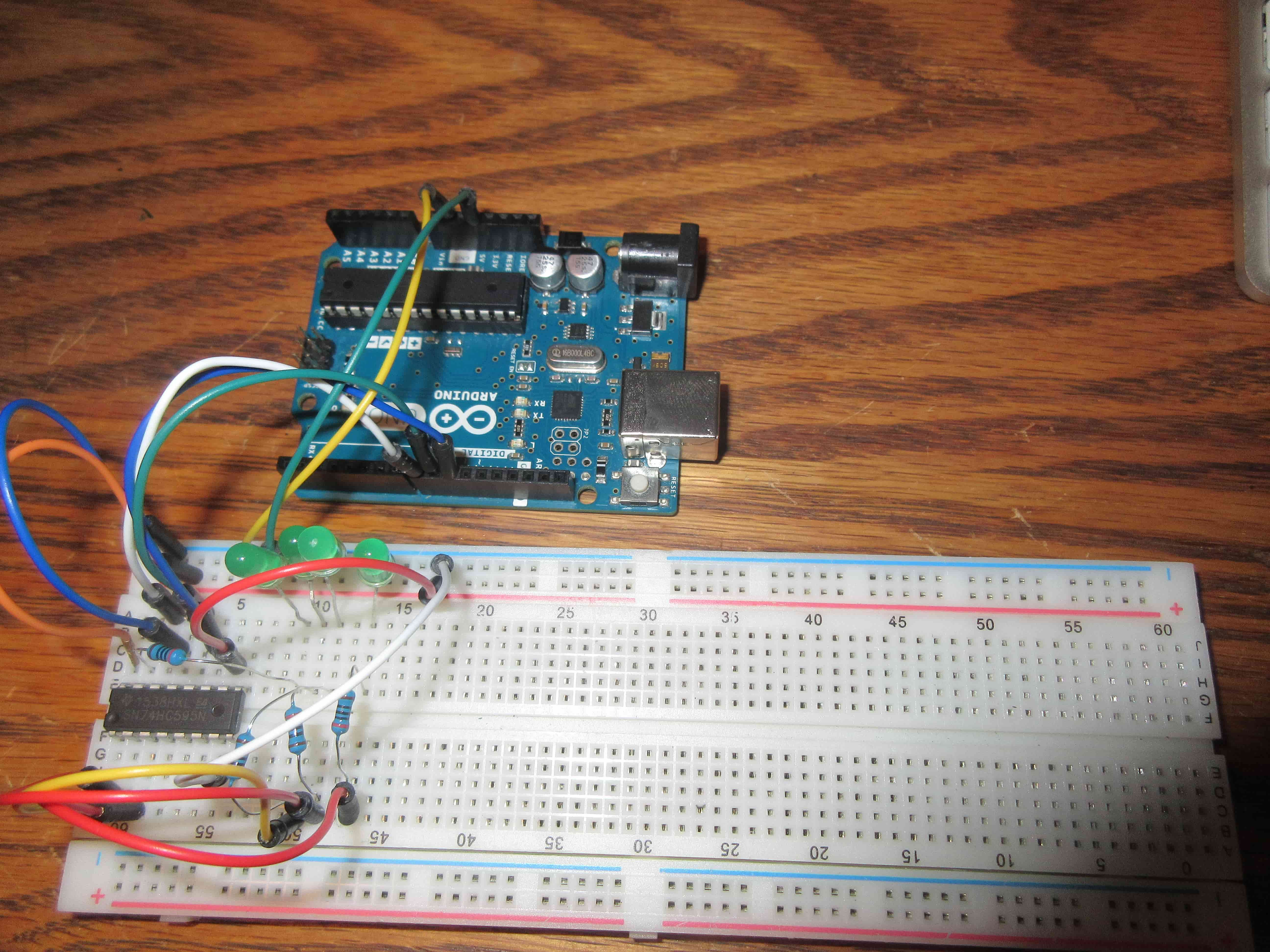
I wired up my arduino uno with the SN74HC595 as shown in the fritzing image, but when I turned it on, all the leds lit up and stayed like that, instead of blinking. I've tried a different chip, a different breadboard, and different code, but it doesn't work. What am I doing wrong? (The fritzing sketch isn't very clear, 4 leds are connected to outputs 0-3, MR is high and OE is low, and Data goes to arduino pin 8, latch to pin 9 through a 0.1uf cap to ground, and clock goes to pin 10)

int latchPin = 9;
int clockPin = 10;
int dataPin = 8;

void setup() {
  pinMode(latchPin, OUTPUT);
  pinMode(clockPin, OUTPUT);
  pinMode(dataPin, OUTPUT);
}

void loop() {
    digitalWrite(latchPin, LOW);
    shiftOut(dataPin, clockPin, MSBFIRST, 0b11111111);
    digitalWrite(latchPin, HIGH);
    delay(100);
    digitalWrite(latchPin, LOW);
    shiftOut(dataPin, clockPin, MSBFIRST, 0b00000000);
    digitalWrite(latchPin, HIGH);
    delay(100);
}

Thanks so much for helping! The fritzing file is attached.

Get rid of that little capacitor (the one going from IC pin 12 to Gnd).

Your LEDs don't have resistors (N.G.)

Did you get that cap from this example.

The cap there is WRONG, and this should have been corrected 10 years ago.
There are unfortunately more of these uncorrected blunders in the guides of this site.
Leo..

I removed the capacitor and when I plugged it back in, it still didn't work and all the leds are lit.
Also, the leds do have resistors, but I forgot to put them in the picture.

Are they flickering very fast?
The LEDs are only on for 0.1second, then off for 0.1 second.
Change the delays to (1000)
Leo..

I changed the code, but it is still constantly on. Is there anything wrong with my wiring (Besides the aforementioned issues)?

We didn't see your wiring yet.
A fritzing diagram is useless. Post a real picture of the layout.
Leo..

I attached the picture of the wiring on the original post. Thanks.

TomRoot:
I attached the picture of the wiring on the original post. Thanks.

No you didn't, you attached a Fritzing physical layout and a photograph. We need to see a schematic in order to give advice.


^^ Any advice? ^^

Check the wiring of these:
int latchPin = 9; >> HC595 pin 12
int clockPin = 10; >> HC595 pin 11
int dataPin = 8; >> HC595 pin 14
Add a 0.1uF cap from 16 to Gnd.