UPDATE: NOW SUPPORTS EITHER ARDUINO WIFI 101 SHIELD OR ARDUINO ETHERNET SHILED
REFER TO THIS POST FOR DETAILS SHARED BETWEEN THE TWO PROJECTS
REFER TO POST #3 FOR DETAILS ON JUST THE WIFI VERSION
i have been working on a home project to automate the control of my ball python cage. the cage has three under-the-tank heaters, humidifier, heat lamp, and UV light.
the arduino system is composed of the following:
Arduino Mega 2560
Arduino Ethernet Shield
RTC Module
5x onewire temperature sensors
2x humidity sensors
6 relays
SD card in the Ethernet shield
7.5 volt power for the arduino
5 volt power for the relay coils
2x humidifier
humidifier air pump
3x under-the-tank heaters
heat lamp
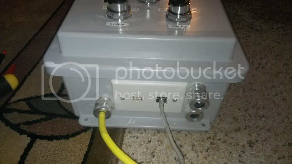
with airtight / water tight Hoffman enclosure (ebay, no link available)
the system is controlled and monitored through a web server running on the arduino. the system has 9 different pages:
1.) System Overview -- allows the user to see the current temperatures from the 5 onewire sensors, the average cage ambient temperature (average of sensors 4 and 5), to see if the sensors are currently functioning, the status of the relays (on/off) and the average humidity within the cage
The images used to signify if the relays are on/off as well as the images used to signify if the temperature sensors are good/bad are stored on the SD card and read off the SD card.

2.)Temperature Adjust - allows the user to configure the system to use either degrees F or degrees C as the temp scale. It also allows the user to control the on/off temperature settings for the three under-the-tank heaters connected to relays 1 through 3, and the heat lamp connected to relay 4. the settings can be configured for both day-time and night-time to simulate lower temperatures at night if the user desires
all data entry areas have logic to determine if the entered values are acceptable. if they are not, the web-page details the issue the user
all user settings are saved to EEPROM


3.)Humidity Adjust - allows the user to configure the system's humidifier on/off settings for both day time and night time
all data entry areas have logic to determine if the entered values are acceptable. if they are not, the web-page details the issue the user
all user settings are saved to EEPROM

4.)Date/Time Adjust - allows the user to set the system's day, month, year, day of the week, and time zone. the system also allows for the hour, minute, and seconds to be updated over the internet through a NTP server. the code is written so a specific IP is not required for the NTP server. instead it uses DNS to resolve the IP of time.nist.gov as it is resolved to all of the server addresses in a round-robin sequence to equalize the load across all of the servers. the system automatically always connects to the internet every 24 hours to update its time again to correct for any drift associated with the RTC
The page also allows the user to configure when the UV light turns off and on signifying when the system considers it either "day time" or "night time"
all user settings are saved to EEPROM

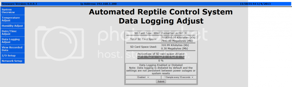
5.)Data Logging Adjust - allows the user to enable or disable data logging, allowing the system to log one sample every 10, 20, 30, 40, 50, or 60 seconds.
This page also explains all the details of the SD card inserted into the Ethernet shield
if no SD card is present, it will tell you and prevent the user from data logging.
if the SD card is present, but not formatted, it will tell the user and prevent data logging
if the SD card is present, formatted, but cannot be accessed for one reason or another it will tell the user and prevent data logging
it tells the user the size of the SD card in kilobytes and megabytes
it tells the user the amount of space used on the SD card in both kilobytes and megabytes, verified to read the same value as windows explorer
it has a progress bar that shows the percentage of SD card space used
data logging enable/disable settings are not saved to EEPROM. data logging must be enabled manually every time the system powers up.
allows for the log files to be individually deleted off the SD card if desired (image does not show this part of the form as i have not updated the image i am using in this post ![]() ). at 1 sample per 10 seconds, 24 hours of recording equates to approximately 3250 plus or minus 20 kB.
). at 1 sample per 10 seconds, 24 hours of recording equates to approximately 3250 plus or minus 20 kB.
6.)View Recorded Data - lists all the log files on the SD card so the data can be viewed and downloaded by the user. the system creates a different log file every day of logging is enabled. the files are named for the month, day and year so the user can easily look back at what happened with the system at a specific time with ease.


7.)I/O Setup- allows the user to decide how the 6 relays are controlled - either automatic, or manual. each relay can be configured independently. when the relay is set for manual control, then the user can press a button to turn it on or off
when the system powers up, all relays are configured to be controlled by the system by default. any time the system restarts, resets, or is power cycled, the relays would have to be set back to manual control if manual control is desired.


8.)Network Setup - allows the user to configure the system for static settings or DHCP. even if using DHCP, the system shows the user the IP address, subnet mask, default gateway, and DNS server. if the system is using static settings, all user settings are saved to EEPROM

9.)System Information - gives a system up-time counter in years, months, days, hours, seconds. also displays the MAC address of the system. Displays if there were any instances in which the temperature sensors malfunctioned. any time any sensor malfunction is detected, the counter will increase. The system will also send an e-mail indicating to the user that a sensor is not working and needs to be checked. finally, displays the available system RAM
latest code revision:
https://www.dropbox.com/s/uxf89wcth826cj0/2.0%206-6-2016%20experimental.zip?dl=0
NOTE: POST WAS UPDATED WITH THE LATEST INFORMATION AVAILABLE. PREVIOUS INFORMATION WAS REPLACED AS REQUIRED.


