Why is my PWM signal not being amplified by the LM386 amp?

I am officially puzzled. I have been following this tutorial to add sound effects to my project:

Then amplified it using a single NPN resistor and 100-ohm resistor, as suggested by this site:

Thanks to those sites, I can play sound effects that sound, really, really good for a single PWM pin. I even hooked the speaker between the NPN collector and +5V to boost the output noticeably, as mentioned in the comments. It was audible in a quiet room, but I was hoping to get just a little bit louder. So I followed this instruction on an LM386 amp, thinking that it could do the trick:

But, oddly, it is not as loud as my simple NPN transistor! I can just barely hear the sound at 20 gain, then when I punch it up to 200 gain, it is still not as loud as the NPN and more distorted too. Even at quiescent levels, the LM386 is consuming around 40mA, which is about the same as the NPN. How can a single transistor do better than a full op amp?

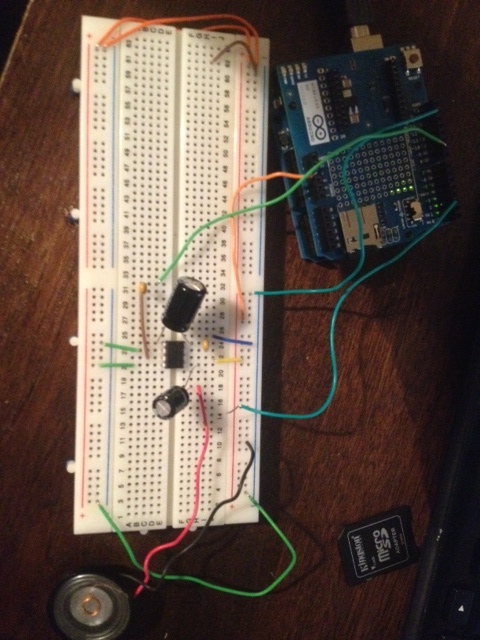
I've tried this with and without capacitors on inputs and outputs. No help. I've tried multiple LM386's too. I am using a small 8-ohm speaker I got from Radio Shack. But it has a pretty strong magnet and I have heard it run louder using a GinSing board. Picture of my breadboard attached.

Do I need a DAC output? How would this help? Should I filter the input to the LM386 to give it sine waves instead of square waves? Would this allow the LM386 to actually amplify the signal like I expect? Why?

Power is calculated as Voltage x Current.* With 5V across 8 Ohms (ignoring the small voltage drop across the transistor), you get 626mA (5V / 8 Ohms = 0.625) . That's about 3 Watts. But, with constant 5 VDC you don't get any sound. You'll get maximum sound at 50% PWM (a square wave), so that's about 1.5 Watts.

You don't get that much out power of an LM386. Once you have a full-power square wave, increasing the "gain" can't get you any more voltage (or current). i.e. You can't turn a 50W amplifier into a 100W amplifier by simply changing a resistor to boost the gain. :wink:

So the simplest solution is to run the transistor from a higher voltage. A 12V square wave into 8 Ohms is about 9 Watts. It's also a good idea to put a capacitor in series with the speaker (maybe a 1000uF electrolytic). The capacitor will block the DC component so at 100% PWM you don't get 18 watts of silent DC frying your speaker.

The general advantage to an amplifier (like the 386) is that it's linear.... You can put a sine-wave in and you get a sine wave out, or you can put a small signal in and get a small signal out. You don't need that with PWM, since PWM is always a full-voltage pulse.

A sine wave is less power than a square wave with an equal peak. Plus, a square wave sounds louder because of the harmonics.

  • You can also calculate power as Voltage squared/Resistance, or Current Squared x Resistance

Great reply!

So to clarify, I will ditch the LM386 and just boost the voltage source powering the speaker via the NPN transistor. That's easy. I was worried about the Emitter-Base Voltage spec max of 6V for my BC547B NPN, but I think that is referring to a voltage being driven on the emitter from elsewhere.

How did you choose the 1000uF value for the capacitor on the output?

I don't understand your comment about the linearity of the LM386... sine wave in, sine wave out and small signal in, small signal out??

I suppose that gain is only useful for boosting very weak signals, not boosting already maxed-out signals?

How did you choose the 1000uF value for the capacitor on the output?

Just from experience with audio amplifiers... Basically a "typical value" for an amplifier driving a speaker. Actually that's on the big side for this application. 100uF should also be OK. There's no harm in using a big capacitor in this application, it's just bulkier and more expensive.

[u]Capacitive Reactance[/u] (in Ohms, like resistance) is inversely related to frequency. Xc = 1/(2Pi x F x C). Note that "C" is in Farads and normal everyday capacitors are rated in microfarads or picofarads. For lower frequencies (bass) you need a bigger capacitor. At higher frequencies, you can get away with a smaller capacitor. And, at lower impedance, you need a bigger capacitor. To keep from loosing voltage across the capacitor, the capacitive reactance should ideally be 1/10th or less of the 8-Ohm speaker. You don't need the full audio range (the Arduino's PWM frequency is around 400Hz) so you can use a smaller value (I'll let you do the calculations, if you wish).

I don't understand your comment about the linearity of the LM386... sine wave in, sine wave out and small signal in, small signal out??

Let's say you have an amplifier with a gain of 10 (and we'll pretend there are no voltage limits). If you put-in 1V, you get out 10V. If you put in 2V, you get out 20V.

A transistor (or MOSFET) in a switching circuit is either full-on, or full-off. If you run a sine-wave into your transistor, you'll get a square wave out (actually a rectangular wave, depending on the voltage of the sine wave and the switching-point of the transistor).

Of course, you can build a linear amplifier with transistors, but it takes a few more components. And, a power amplifier (to drive a speaker) usually has two output transistors.

If you put a pot (volume control) between the Arduino and the transistor, it will essentially work like a switch... When you turn the volume down past a certain point, the sound will suddenly go from full volume to silence. (A transistor isn't a perfect switch, but it will be very hard to control the volume.) If you put a pot between the Arduino and an amplifier, it will actually control the volume.

I suppose that gain is only useful for boosting very weak signals, not boosting already maxed-out signals?

Exactly! If you "max out" an audio amplifier, sine waves start getting "clipped" (distorted, with squared-off positive & negative peaks) until eventually sine waves are almost converted to square waves.

Lots of good information. Thanks for sharing!