I recently purchased the 3.95' variation of this screen from AliExpress but cannot find any documentation for this specific screen/driver. My screen is exactly the same as the one in the pictures. The screen claims to be an ILI9488 but the pins on the screen are labelled differently to the pins on any ILI9488 datasheet. The first difference being the lack of any IM{2:0} pins to configure the MIPI-DBI operating mode (pages 19-20 of data sheet, link below). All the datasheets for similar LCD screens (ILI9XXX) have the same issue.
https://www.aliexpress.com/item/3-8-3-95-inch-320-480-TFT-Color-LCD-Display-Module-Screen-ILI9486-9488-Drive/32916041971.html?spm=a2g0s.9042311.0.0.5e6e4c4d4JvBgv
Any help finding out what the pins on the LCD are and where to find a data sheet for them would be greatly appreciated.
Ah-ha. Do you have the display on you desk?
Please can you read the chip part numbers for U3, U4, U5, U6 and post them here.
Also R1, R2, R3
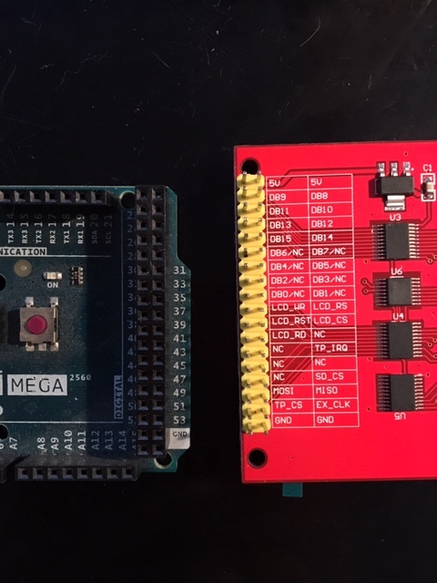
It has all the pins clearly labeled on the pcb.
It "looks" as if it should plug directly into the 18x2 header socket on the Mega2560.
I looks as if it is configured for 8080-8 parallel interface.
David.
@David,
same display as in this post.
My reply #35, #37 in that thread look constructive.
It also looks as if the OP never actually bought that display.
Whereas PilotGuy does seem to have the display in real life !!
When we hear about the part numbers, we can probably get him running with several libraries.
The display looks very promising.
David.
Thanks for the quick replies. The parts are the following:
U3: NXP LVC245A RK23217 TXD716F
U4: NXP LVC245A RK23217 TXD716F
U5: NXP LVC245A RK23217 TXD716F
U6: HR2046 1703
R1: 2R0
R2: 103
R3: 103
Edit: The end goal is to use any libraries and documentation as a reference to program this on an STM32F446RE. Preferably through the SPI interface since many gpios are already in use.
Woo-hoo. NXP LVC245A is the correct input tolerant buffer.
HR2046 is the Touch Controller. XPT2046 equivalent.
- Install MCUFRIEND_kbv and Adafruit_GFX libraries via the IDE Library Manager.
- Plug the Shield into your Mega2560.
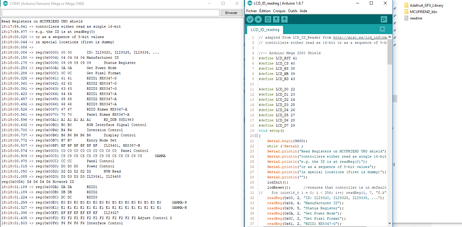
- Edit "LCD_ID_readreg.ino" sketch
//-- Arduino Mega 2560 Shield
#define LCD_RST 41
#define LCD_CS 40
#define LCD_RS 38
#define LCD_WR 39
#define LCD_RD 43

#define LCD_D0 22
#define LCD_D1 23
#define LCD_D2 24
#define LCD_D3 25
#define LCD_D4 26
#define LCD_D5 27
#define LCD_D6 28
#define LCD_D7 29
-
Run the sketch. It should show reg(0xD3) as xx 94 86 xx
-
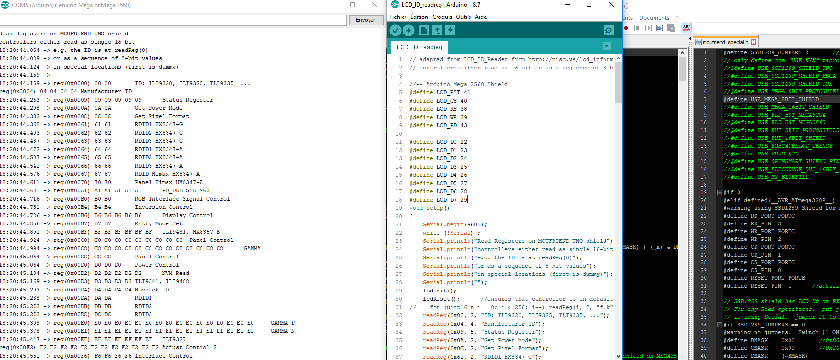
Edit util/mcufriend_shield.h: #define USE_SPECIAL
-
Edit util/mcufriend_special.h: #define USE_MEGA_8BIT_SHIELD
If (4) worked ok, (5), (6) should make your screen work seamlessly with all the MCUFRIEND_kbv examples.
No, the screen has 8080-8 parallel interface. If you want to use SPI, you have to buy the Red ILI9488 SPI board (and provide level shifters)
Please let me know how you get on.
David.
Cheers, The screen works almost flawlessly with the MEGA-2560. The examples appear to be mirrored but I shall try figure that one out on my own. 
Position your screen with the header pins at the top i.e. Portrait.
If the mirror is left-right, change the INVERT_SS attribute in the case 0x9486 block.
If the mirror is top-bottom, change the INVERT_GS attribute.
The case 0x9486 statements are in the MCUFRIEND_kbv.cpp file
The showBMP_Uno example needs to define SD_CS as 48 instead of 10. Make sure that 53 is OUTPUT HIGH. i.e. you can use regular "SD.h" library (which should set 53 as an output by default).
The Touch is completely different. Get TFT and SD tested first.
David.
Back here David ,
Ok i have exactly same screen
RedReg sketch modify :
Read Registers on MCUFRIEND UNO shield
16:15:48.961 -> controllers either read as single 16-bit
16:15:48.995 -> e.g. the ID is at readReg(0)
16:15:49.029 -> or as a sequence of 8-bit values
16:15:49.062 -> in special locations (first is dummy)
16:15:49.130 ->
16:15:49.130 -> reg(0x0000) 00 00	ID: ILI9320, ILI9325, ILI9335, ...
16:15:49.164 -> reg(0x0004) 04 04 04 04	Manufacturer ID
16:15:49.232 -> reg(0x0009) 09 09 09 09 09	Status Register
16:15:49.267 -> reg(0x000A) 0A 0A	Get Power Mode
16:15:49.302 -> reg(0x000C) 0C 0C	Get Pixel Format
16:15:49.335 -> reg(0x0061) 61 61	RDID1 HX8347-G
16:15:49.370 -> reg(0x0062) 62 62	RDID2 HX8347-G
16:15:49.404 -> reg(0x0063) 63 63	RDID3 HX8347-G
16:15:49.438 -> reg(0x0064) 64 64	RDID1 HX8347-A
16:15:49.472 -> reg(0x0065) 65 65	RDID2 HX8347-A
16:15:49.506 -> reg(0x0066) 66 66	RDID3 HX8347-A
16:15:49.540 -> reg(0x0067) 67 67	RDID Himax HX8347-A
16:15:49.574 -> reg(0x0070) 70 70	Panel Himax HX8347-A
16:15:49.642 -> reg(0x00A1) A1 A1 A1 A1 A1	RD_DDB SSD1963
16:15:49.676 -> reg(0x00B0) B0 B0	RGB Interface Signal Control
16:15:49.709 -> reg(0x00B4) B4 B4	Inversion Control
16:15:49.779 -> reg(0x00B6) B6 B6 B6 B6 B6	Display Control
16:15:49.813 -> reg(0x00B7) B7 B7	Entry Mode Set
16:15:49.847 -> reg(0x00BF) BF BF BF BF BF BF	ILI9481, HX8357-B
16:15:49.881 -> reg(0x00C0) C0 C0 C0 C0 C0 C0 C0 C0 C0	Panel Control
16:15:49.949 -> reg(0x00C8) C8 C8 C8 C8 C8 C8 C8 C8 C8 C8 C8 C8 C8	GAMMA
16:15:50.017 -> reg(0x00CC) CC CC	Panel Control
16:15:50.051 -> reg(0x00D0) D0 D0 D0	Power Control
16:15:50.085 -> reg(0x00D2) D2 D2 D2 D2 D2	NVM Read
16:15:50.119 -> reg(0x00D3) D3 D3 D3 D3	ILI9341, ILI9488
16:15:50.153 -> reg(0x00D4) D4 D4 D4 D4	Novatek ID
16:15:50.188 -> reg(0x00DA) DA DA	RDID1
16:15:50.222 -> reg(0x00DB) DB DB	RDID2
16:15:50.257 -> reg(0x00DC) DC DC	RDID3
16:15:50.291 -> reg(0x00E0) E0 E0 E0 E0 E0 E0 E0 E0 E0 E0 E0 E0 E0 E0 E0 E0	GAMMA-P
16:15:50.359 -> reg(0x00E1) E1 E1 E1 E1 E1 E1 E1 E1 E1 E1 E1 E1 E1 E1 E1 E1	GAMMA-N
16:15:50.427 -> reg(0x00EF) EF EF EF EF EF EF	ILI9327
16:15:50.460 -> reg(0x00F2) F2 F2 F2 F2 F2 F2 F2 F2 F2 F2 F2 F2	Adjust Control 2
16:15:50.528 -> reg(0x00F6) F6 F6 F6 F6	Interface Control
With graphictest_kv : screen work
Serial took 0ms to start
ID = 0xD3D3
Please read #5 carefully.
Make notes with pencil and paper.
Post the results in your message. Especially if you do not agree with PilotGuy.
When I am trying to debug a remote screen, I have to rely on accurate reports from the remote user. I know that this requires effort on your part. But at the end of the day I can give 100% advice to new buyers. (and you benefit too)
David.
Ok i make a new fresh IDE installation
i follow steps #5
And same result ( show screen )
Edit : i have cleam arduino Eprom before test
redregwithoutmodify.txt (2.16 KB)
redregwithmodify.txt (2.15 KB)
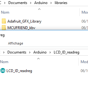
Ouch. You have put "User" libraries in the "System" libraries folder. You will need Administrator privileges to remove them.
- Leave the IDE.
- Please remove your "user" libraries. You should only have the libraries that came with the IDE in "Program Files"
- Start the IDE.
- Run the Library Manager.
- Install Adafruit_GFX and MCUFRIEND_kbv libraries.
Follow the other steps from #5.
I am confused. Your "fresh.png" looks like Windows. Your "reg.txt" does NOT look like the Arduino Serial Terminal.
Your "modify.png" looks correct. It is an Editor "view". Obviously you would need Administrator privileges to save it back to disk.
I strongly recommend that you use a recent IDE version 1.8.x. You do not need to have the latest version.
I am still using v1.8.1 on this PC. I would be VERY surprised if the Library Manager has "changed" in the latest IDE.
The Java IDE will let you edit library files in "User" directories. And use the current library files when building a sketch.
However it builds the read-only example sketch from the lines in IDE editor memory. I suggest that you never alter library examples. Save as a "user" sketch if you modify an example.
David.
I clean again IDE
same output serial monitor
I use the IDE from https://www.arduino.cc/en/Main/Software

I am stumped. You seem to have the libraries in the correct place. I assume that you have removed them from Program Files now.
You also seem to have "Serial Terminal" too. I do not get timestamps. It must make the Terminal unusable.
I use Notepad++ too. It prompts you if there is an Administrator Privilege problem.
You seem to have an unusual User name. "admin" must create all sorts of problems for you.
Libraries, Paths, Privileges, ... can be a little complicated.
"LCD_ID_readreg" only uses pinMode(), digitalWrite(), digitalRead() and Serial.print()
It does not care what libraries or paths are used. It runs on AVR, ARM, ESP32, STM32, ... or any platform that has digitalXXX()
I can only suggest that you abandon this for now.
Wait until PilotGuy replies.
David.
ok i wait reply from PilotGuy
But i have very surpris beacaus GLUE_Demo8480x320 work ...
But backend screen is not black , is white , i dont say why 
Your readreg report implies that LCD_RD pin is not working. If forcing ID = 0x9486 works, it means that the data bus is working but only in write-only mode.
Please compare your pcb with the photos in your link. Especially traces near pin #43.
It is possible that you have an early pcb revision before Surenoo produced PilotGuy's pcb.
Do you get mirroring?
David.
It's same , i buy with excacly same link
david_prentice:
If forcing ID = 0x9486
Hi David ,
Where in sketch can force ID ?
Thanks
Please run steps (2), (3), (4) from message #5.
Then copy-paste from the Serial Terminal to your message.
David.
Read Registers on MCUFRIEND UNO shield
controllers either read as single 16-bit
e.g. the ID is at readReg(0)
or as a sequence of 8-bit values
in special locations (first is dummy)
New info , when run sketch "graphictest_kvb" whith ( line 95 - 96 )
if (ID == 0xD3D3) ID = 0x9481; // write-only shield
I have miroiring
But if run with
ID = 0x9488; // force ID
Screen is correct