Trouble with SPI read/write to 23K256 SRAM chip (SOLVED)

Hi,

EDIT: This may simply have been a defect with the breakout board.

EDIT: It was a bug with the board after all. Was able to get this to function using just dip chips on a breadboard with jumper wire. However note that the level shifter I had available (the 4050) is too slow to run the attached source as is. Changing the line

  SPI.setClockDivider(SPI_CLOCK_DIV2);

to

  SPI.setClockDivider(SPI_CLOCK_DIV32);

and it ran fine (t/y SurferTim).

original post

I'm having issues reading/writing to a 23K256 SRAM chip via SPI. It appears that bytes read are not the ones written.

Environment:
Arduino Uno R3
Arduino IDE 1.05

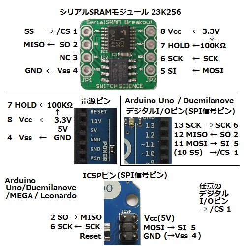
The 23K256 chip is on a small breakout board by Switch Science (Japan) that includes a level shifter on board to allow direct connection to the Arduino.

Sketch (includes pin connection chart in comments):

#include <SPI.h>
#include <SPISRAM.h>

/*
 SRAM   Arduino
 1 CS   10(CS)
 2 SO   12(MISO)
 3 -    -
 4 Vss  GND
 5 SI   11(MOSI)
 6 SCK  13(SCK)
 7 HOLD <-- 100k ohm -- 3.3V
 8 Vcc  3.3V
 */

SPISRAM myRAM(10); // CS pin
char buffer[128];

void setup()
{
  pinMode(5, OUTPUT);
  Serial.begin(9600);

  SPI.begin();
  SPI.setBitOrder(MSBFIRST);
  SPI.setClockDivider(SPI_CLOCK_DIV2);
  SPI.setDataMode(SPI_MODE0);

  Serial.println("Byte write...");
  myRAM.write(0,'H');
  myRAM.write(1,'e');
  myRAM.write(2,'l');
  myRAM.write(3,'l');
  myRAM.write(4,'o');
  myRAM.write(5,'-');

  Serial.println("Byte read...");
  Serial.println(myRAM.read(0));
  Serial.println(myRAM.read(1));
  Serial.println(myRAM.read(2));
  Serial.println(myRAM.read(3));
  Serial.println(myRAM.read(4));
  Serial.println(myRAM.read(5));

  Serial.println("\nByte write...");
  myRAM.write(0x7FFC,'W');
  myRAM.write(0x7FFD,'o');
  myRAM.write(0x7FFE,'r');
  myRAM.write(0x7FFF,'l');
  myRAM.write(0x8000,'d');
  myRAM.write(0x8001,'!');
  myRAM.write(0x8002,'!');

  Serial.println("Byte read...");
  Serial.println(myRAM.read(0x7FFC));
  Serial.println(myRAM.read(0x7FFD));
  Serial.println(myRAM.read(0x7FFE));
  Serial.println(myRAM.read(0x7FFF));
  Serial.println(myRAM.read(0x8000));
  Serial.println(myRAM.read(0x8001));
  Serial.println(myRAM.read(0x8002));

  Serial.println("\nseq write...");
  int addr = 0x7F00;
  myRAM.write(addr, (byte*)"Hello world!!", sizeof("Hello world!!"));

  Serial.println("seq read...");
  myRAM.read(addr, (byte*)buffer, sizeof(buffer));
  Serial.println( buffer );

  Serial.println("\nByte read at operator[]...");
  myRAM[100] = 'H';
  myRAM[101] = 'e';
  myRAM[102] = 'l';
  myRAM[103] = 'l';
  myRAM[104] = 'o';
  Serial.println( myRAM[100] );
  Serial.println( myRAM[101] );
  Serial.println( myRAM[102] );
  Serial.println( myRAM[103] );
  Serial.println( myRAM[104] );

  Serial.println("\nRandom read/write...");
  for(int i=0;i<100;i++){
    int addr = random() & 0x7fff;
    byte val = i;
    Serial.print( addr, HEX );
    Serial.print( " " );
    Serial.print( val, HEX );
    myRAM[addr] = val;
    Serial.print( " " );
    Serial.println( myRAM[addr], HEX );
  }
}

void loop()
{
}

The SPISRAM library used is as follows.

/*
  Copyright (c) 2010 by arms22 (email redacted)
  Microchip 23x256 SPI SRAM library for Arduino
  
  This library is distributed in the hope that it will be useful,
  but WITHOUT ANY WARRANTY; without even the implied warranty of
  MERCHANTABILITY or FITNESS FOR A PARTICULAR PURPOSE. 
*/

#ifndef SPISRAM_H
#define SPISRAM_H

#include <SPI.h>

class SPISRAM
{
public:
	struct MemCell {
		SPISRAM &device;
		unsigned int address;
		MemCell &operator=(byte data){
			device.write(address,data);
			return *this;
		}
		operator byte() {
			return device.read(address);
		}
		MemCell(SPISRAM &d,unsigned int a) : device(d), address(a) {};
		~MemCell(){};
	};
	MemCell operator[](unsigned int address){
		MemCell memcell(*this,address);
		return memcell;
	}
	SPISRAM(byte ncsPin);
	byte read(unsigned int address);
	void read(unsigned int address, byte *buffer, unsigned int size);
	void write(unsigned int address, byte data);
	void write(unsigned int address, byte *buffer, unsigned int size);
private:
	byte _ncsPin;
	byte _buf[4];
	void select(void);
	void deselect(void);
	byte transfer(byte length);
};

#endif
/*
  Copyright (c) 2010 by arms22 (email redacted)
  Microchip 23x256 SPI SRAM library for Arduino
  
  This library is distributed in the hope that it will be useful,
  but WITHOUT ANY WARRANTY; without even the implied warranty of
  MERCHANTABILITY or FITNESS FOR A PARTICULAR PURPOSE. 
*/

#include "SPISRAM.h"

// INSTRUCTION SET
#define READ	0x03			// Read data from memory
#define WRITE	0x02			// Write data to memory
#define RDSR	0x05			// Read Status register
#define WRSR	0x01			// Write Status register

// STATUS REGISTER
#define	BYTE_MODE	0x00
#define	PAGE_MODE	0x80
#define SEQ_MODE	0x40

SPISRAM::SPISRAM(byte ncsPin)
	: _ncsPin(ncsPin)
{
}

byte SPISRAM::read(unsigned int address)
{
	_buf[0] = READ;
	_buf[1] = address >> 8;
	_buf[2] = address & 0xff;
	_buf[3] = 0x00;
	return transfer(4);
}

void SPISRAM::read(unsigned int address, byte *buffer, unsigned int size)
{
	_buf[0] = WRSR;
	_buf[1] = SEQ_MODE;
	transfer(2);
	select();
	SPI.transfer(READ);
	SPI.transfer(address >> 8);
	SPI.transfer(address & 0xff);
	for(unsigned int i=0; i<size; i++){
		*buffer++ = SPI.transfer(0);
	}
	deselect();
}

void SPISRAM::write(unsigned int address, byte data)
{
	_buf[0] = WRITE;
	_buf[1] = address >> 8;
	_buf[2] = address & 0xff;
	_buf[3] = data;
	transfer(4);
}

void SPISRAM::write(unsigned int address, byte *buffer, unsigned int size)
{
	_buf[0] = WRSR;
	_buf[1] = SEQ_MODE;
	transfer(2);
	select();
	SPI.transfer(WRITE);
	SPI.transfer(address >> 8);
	SPI.transfer(address & 0xff);
	for(unsigned int i=0; i<size; i++){
		SPI.transfer(*buffer++);
	}
	deselect();
}

void SPISRAM::select(void)
{
	digitalWrite(_ncsPin, LOW);
}

void SPISRAM::deselect(void)
{
	digitalWrite(_ncsPin, HIGH);
}

byte SPISRAM::transfer(byte length)
{
	byte ret,i;
	select();
	for(i=0; i<length; i++){
		ret = SPI.transfer(_buf[i]);
	}
	deselect();
	return ret;
}

And the serial output looks like this. I would expect the serial output to start with the same characters that were written, particularly with the sequential read/write operation returning the character string "Hello world!!". However, I get seemingly random characters: (Ø×aD?

Byte write...
Byte read...
1
66
81
81
92
16

Byte write...
Byte read...
26
93
97
81
64
0
1

seq write...
seq read...

(Ø×aD?

Byte read at operator[]...
1
66
81
81
94

Random read/write...
41A7 0 0
3AF1 1 0
2CD9 2 0
C2A 3 2
3782 4 1
5AC8 5 1
ED8 6 4
9FE 7 6
2F43 8 0
44D 9 0
1898 A 1
3C55 B 5
128C C 8
5BE2 D 8
54B3 E C
3747 F F
3917 10 0
4111 11 1
4398 12 3
4954 13 7
2E2F 14 0
2B11 15 0
162D 16 B
B05 17 C
3258 18 10
66F5 19 10
16B 1A 10
1DD6 1B 17
7788 1C 18
1D07 1D 19
6499 1E 1C
3492 1F 1E
F48 20 0
5133 21 1
6E62 22 0
1441 23 6
4CF3 24 0
F0D 25 3
5023 26 8
6AE5 27 C
785F 28 0
3530 29 2
22D1 2A 0
76C8 2B B
75ED 2C 13
4561 2D 13
680C 2E 18
154B 2F 1E
2902 30 20
5435 31 20
39 32 22
5081 33 26
6484 34 20
25B8 35 22
6514 36 28
1BA2 37 2C
339C 38 31
66B4 39 30
6E5A 3A 32
1267 3B 34
2C2A 3C 38
34CA 3D 38
5AE5 3E 3D
1248 3F 3E
49E9 40 0
20C5 41 0
5F1 42 3
22B0 43 4
56C4 44 0
1C15 45 2
2B8A 46 9
11E5 47 E
6A9B 48 0
784D 49 3
4339 4A 2
75F6 4B F
7F7 4C 12
26E8 4D 11
4CA1 4E 18
1005 4F 1E
6AD3 50 0
78FE 51 3
73ED 52 0
4DA5 53 8
38D5 54 7
60F3 55 0
1AD9 56 17
4CE4 57 1C
3C5B 58 23
3BFA 59 23
546C 5A 20
DC3 5B 28
1151 5C 30
73E2 5D 32
1C20 5E 39
1FAE 5F 3F
100C 60 40
1EE1 61 41
7D06 62 43
2698 63 44

Please let me know if any of you have an idea what I'm doing wrong. Thanks!

Edit: By the way, following manufacturer spec (Switch Science) I have a 100K resistor between VCC and pin 7, so that isn't the cause from what I can see (apparently that is a common error).

A pic of the breakout board and pin diagram can be found here: http://docid81hrs3j1.cloudfront.net/contents/cms/10121702_5077ce9567a88.jpg

Try slowing down the SPI bus just as a test. Maybe it is a bit too high for "breadboard" type wiring.

  SPI.setClockDivider(SPI_CLOCK_DIV4);

edit: Maybe the 100K resistor is not enough current to pin 7. Try a smaller value, like 10K.

Thanks, unfortunately neither change caused any change in the serial output.

Have you tried just a basic write and read? That random thing at the end of your code may be just that.

Try this code:

#include <SPI.h>
#include <SPISRAM.h>

/*
 SRAM   Arduino
 1 CS   10(CS)
 2 SO   12(MISO)
 3 -    -
 4 Vss  GND
 5 SI   11(MOSI)
 6 SCK  13(SCK)
 7 HOLD <-- 100k ohm -- 3.3V
 8 Vcc  3.3V
 */

SPISRAM myRAM(10); // CS pin
char buffer[128];

void setup()
{
  pinMode(5, OUTPUT);
  Serial.begin(9600);

  SPI.begin();
  SPI.setBitOrder(MSBFIRST);
  SPI.setClockDivider(SPI_CLOCK_DIV4);
  SPI.setDataMode(SPI_MODE0);

  Serial.println("Byte write...");
  myRAM.write(0,'H');
  myRAM.write(1,'e');
  myRAM.write(2,'l');
  myRAM.write(3,'l');
  myRAM.write(4,'o');
  myRAM.write(5,' ');

  Serial.println("Byte read...");
  Serial.println(myRAM.read(0));
  Serial.println(myRAM.read(1));
  Serial.println(myRAM.read(2));
  Serial.println(myRAM.read(3));
  Serial.println(myRAM.read(4));
  Serial.println(myRAM.read(5));
}

void loop()
{
}

Thanks again, but not this has no effect. I still get garbled output:

Byte write...
Byte read...
1
66
81
81
92
0

So here, the first and last byte are incorrect, while the "ello" is at least coming back as the correct ascii codes, which happens every other time as well (though I don't understand why it is output as integers instead of char).

So the issue is that some of the bytes are being written and read, but that somehow the SRAM chip is weirding out at the start of the write operation (and the end?).

Try connecting the HOLD pin to 3.3v directly. If you are uncomfortable with that, use a very small value resistor, like 1K or smaller. Here is a quote from another user trying to get the gibberish problem solved.

However, I couldn’t get the chip to function. My test program was returning values, but they were gibberish. Something was clearly wrong.

I experimented over the course of several days with substituting an Adafruit TXB0108 Bidirectional Level Shifter. I searched the web and discovered many people had similar problems getting these chips to operate. I even tried using a few resister pair/voltage dividers in place of the level shifter. I began to get very skeptical of anyone that claimed they made these chips work. I searched the web some more and re-read the datasheet (there’s also a Microchip Application Note). I added a 10K ohm pull-up resister to the CS pin, but still gibberish.

Eventually I swallowed my pride and wrote a “help-wanted” post on the Arduino Forum. A few responses later I recieved a solution! I needed to tie the 23K256 HOLD pin high. While the datasheet doesn’t specifically state that, after countless re-readings I’ll admit it hints at it.

My assumption from reading that blog ( Interfacing Microchip 23K256 32KB SRAM SPI Memory with Arduino | µC eXperiment ) before I posted my question here was that he had a resistor between VCC and HOLD, but it does appear that he just hooked that pin directly to 3.3V. The documentation I had, as mentioned in the sketch source comments above, explicitly states that a 100k resister between VCC and HOLD is required. Interestingly, removing it entirely and connecting HOLD to 3.3V directly has no effect for my setup.

I've tested two of these 23k256 breakout boards from this manufacturer with identical results. I'm still waiting for more help from the manufacturer, and I've been promised a reply within the next couple of days.

I also have a few through hole versions of the chip w/o breakout boards, so I might try testing the circuit using level shifters I have on hand to see if there is anything different (might help isolate the issue).

Edit: I also take this blog post with a grain of salt seeing as he has the Arduino's 3.3V pin connected to CS on the SRAM chip, which makes me wonder if he knows what CS is for. Maybe he figures he has only this one component on the SPI bus so it doesn't matter, but I would still think this would be a technically incorrect setup.

I also take this blog post with a grain of salt seeing as he has the Arduino's 3.3V pin connected to CS on the SRAM chip, which makes me wonder if he knows what CS is for.

He stated why he did that. The CS pin is connected to 3.3v with the 10K resistor as a weak pullup. That should not be a problem either way.

Let us know what you find out from the manufacturer. That might be a handy IC for me someday.

My understanding is that the point of the SPI interface is to allow communicating with multiple devices using a minimum of pins, so connecting CS to voltage out does not seem like good practice IMHO, even if it may work, because it means you cannot add other SPI devices without rewiring.

I'll post whatever reply I get from the manufacturer.

My understanding is that the point of the SPI interface is to allow communicating with multiple devices using a minimum of pins, so connecting CS to voltage out does not seem like good practice IMHO, even if it may work, because it means you cannot add other SPI devices without rewiring.

That is not correct. He connected CS to 3.3v with a 10K resistor. That is just a weak pullup to keep the device from booting with the SPI active. The SRAM CS pin is still connected directly to the Arduino pin, and should allow multiple devices on the SPI bus.

I would like to know if you get this working. Nice addition to the parts inventory for the Arduino. Data memory is the one thing that is in short supply.

Ah, OK. TIL. I went ahead and added a 10K resistor on CS to my setup as well, but still no change. The first and last characters of "hello" are still getting garbled.

One thing I hadn't noticed, there is also a surface mount capacitor on the board between Vcc and Vss, as per the chip maker's data sheet, so it isn't just the SRAM chip and the level shifter.

I'll let you know what the board maker says.

Just a thought. Since it is just the first and last character garbled, try adding a microsecond delay to your library on the select and deselect calls. Like this. What could it hurt at this point, right?

void SPISRAM::select(void)
{
    digitalWrite(_ncsPin, LOW);

// add this
    delayMicroseconds(1);
}

void SPISRAM::deselect(void)
{
// add this
    delayMicroseconds(1);

    digitalWrite(_ncsPin, HIGH);
}

That's an interesting angle, but unfortunately that also had no effect, so it probably isn't the timing. Which is actually reassuring, because the application I want to use this for is in an Arduino based Shoutcast client. The idea to use the SRAM comes from a guy in Japan who's managed to play back at least 128Kbps streams on a breadboard Uno equivalent (which he subsequently made a shield for which I'm not using because it has everything on one board, including a few components I would rather replace with others) by altering the Ethernet library and writing to SRAM from the ethernet chip's buffer, and from there to the MP3 player. Requiring a delay could mess with the timing and make the higher bit rate streams harder to read, I imagine, because he really struggled to get the throughput high enough to play those streams.

http://www.geocities.co.jp/orion_cosmo/irshield.html

Just a heads up here, the manufacturer has contacted me stating that it may be a defect in the product (probably the board). I'll update again if that is in fact the case.

The manufacturer sent me three new breakout boards, but they all had the same issue (assuming it wasn't something I'm doing all along).

So I've gone ahead and wired up the same thing on a breadboard using loose parts, using the 23K256 DIP package and a 4050 for level shifting.

I've got a different odd result, but at least now I am reading consistently and predictably. Basicly, the values I write are being halved, so I'm reading back half the ascii value for each char I write (even rounded down, such as 'e', 101, becoming 50). I'm assuming I'm doing something silly with the level shifter, so I'll muck about with the datasheet and see what I can come up with.

Byte write...
Byte read...
36
50
54
54
55
22

Byte write...
Byte read...
43
55
57
54
50
16
16

seq write...
seq read...
$2667;7962

Byte read at operator[]...
36
50
54
54
55

Random read/write...
41A7 0 0
3AF1 1 0
2CD9 2 1
C2A 3 1
3782 4 2
5AC8 5 2
ED8 6 3
9FE 7 3
2F43 8 4
44D 9 4
1898 A 5
3C55 B 5
128C C 6
5BE2 D 6
54B3 E 7
3747 F 7
3917 10 8
4111 11 8
4398 12 9
4954 13 9
2E2F 14 A
2B11 15 A
162D 16 B
B05 17 B
3258 18 C
66F5 19 C
16B 1A D
1DD6 1B D
7788 1C E
1D07 1D E
6499 1E F
3492 1F F
F48 20 10
5133 21 10
6E62 22 11
1441 23 11
4CF3 24 12
F0D 25 12
5023 26 13
6AE5 27 13
785F 28 14
3530 29 14
22D1 2A 15
76C8 2B 15
75ED 2C 16
4561 2D 16
680C 2E 17
154B 2F 17
2902 30 18
5435 31 18
39 32 19
5081 33 19
6484 34 1A
25B8 35 1A
6514 36 1B
1BA2 37 1B
339C 38 1C
66B4 39 1C
6E5A 3A 1D
1267 3B 1D
2C2A 3C 1E
34CA 3D 1E
5AE5 3E 1F
1248 3F 1F
49E9 40 20
20C5 41 20
5F1 42 21
22B0 43 21
56C4 44 22
1C15 45 22
2B8A 46 23
11E5 47 23
6A9B 48 24
784D 49 24
4339 4A 25
75F6 4B 25
7F7 4C 26
26E8 4D 26
4CA1 4E 27
1005 4F 27
6AD3 50 28
78FE 51 28
73ED 52 29
4DA5 53 29
38D5 54 2A
60F3 55 2A
1AD9 56 2B
4CE4 57 2B
3C5B 58 2C
3BFA 59 2C
546C 5A 2D
DC3 5B 2D
1151 5C 2E
73E2 5D 2E
1C20 5E 2F
1FAE 5F 2F
100C 60 30
1EE1 61 30
7D06 62 31
2698 63 31

How do you have the 4050 connected? You should have the 4050 powered by 3.3v and only the SS, MOSI and SCK connected to the 4050. The 23K256 MISO line can go directly to the Arduino.

I see a lot of products use the 74LVC245 as a logic level converter now. It appears to be about 10 times faster than the 4050.

edit: The uSD card slot on the ethernet shield uses a 74LVC1G125DCK as a converter. It works good.

Yes, I just have SS, MOSI, and SCK running through it, with 3.3v in on pin 1 and ground on 8. As far as I can tell from the datasheet, it appears that pins 3, 5, and 7 going down the left are in, while the corresponding out pins are 2, 4, and 6 respectively. I imagine it would be a problem if I had that wrong. Apparently these are not bidirectional, but I guess that doesn't matter for the 23K256, so long as I have it wired correctly.

That is correct. My only concern is the propagation delay of the 4050. 120ns is a bit slow for the Arduino. You might want to cut the SPI bus speed down considerably, just as a test. You can always set it back if it makes no difference.

SPI.setClockDivider(SPI_CLOCK_DIV32);

Brilliant, that did it.

So,

  1. I don't need a breakout board. Chips and jumper wires will do fine until if and when I make my own board for the project.
  2. I definitely need to level shift faster than the 4050. You said the 74LVC245 is good? The whole point of the setup is the speed gain this potentially gives me so I can get the mp3 stream from ether to mp3 chip fast enough for it to play.

Do you know of any other fast level shifters off hand?

And the serial output:

Byte write...
Byte read...
72
101
108
108
111
45

Byte write...
Byte read...
87
111
114
108
100
33
33

seq write...
seq read...
Hello world!!

Byte read at operator[]...
72
101
108
108
111

Random read/write...
41A7 0 0
3AF1 1 1
2CD9 2 2
C2A 3 3
3782 4 4
5AC8 5 5
ED8 6 6
9FE 7 7
2F43 8 8
44D 9 9
1898 A A
3C55 B B
128C C C
5BE2 D D
54B3 E E
3747 F F
3917 10 10
4111 11 11
4398 12 12
4954 13 13
2E2F 14 14
2B11 15 15
162D 16 16
B05 17 17
3258 18 18
66F5 19 19
16B 1A 1A
1DD6 1B 1B
7788 1C 1C
1D07 1D 1D
6499 1E 1E
3492 1F 1F
F48 20 20
5133 21 21
6E62 22 22
1441 23 23
4CF3 24 24
F0D 25 25
5023 26 26
6AE5 27 27
785F 28 28
3530 29 29
22D1 2A 2A
76C8 2B 2B
75ED 2C 2C
4561 2D 2D
680C 2E 2E
154B 2F 2F
2902 30 30
5435 31 31
39 32 32
5081 33 33
6484 34 34
25B8 35 35
6514 36 36
1BA2 37 37
339C 38 38
66B4 39 39
6E5A 3A 3A
1267 3B 3B
2C2A 3C 3C
34CA 3D 3D
5AE5 3E 3E
1248 3F 3F
49E9 40 40
20C5 41 41
5F1 42 42
22B0 43 43
56C4 44 44
1C15 45 45
2B8A 46 46
11E5 47 47
6A9B 48 48
784D 49 49
4339 4A 4A
75F6 4B 4B
7F7 4C 4C
26E8 4D 4D
4CA1 4E 4E
1005 4F 4F
6AD3 50 50
78FE 51 51
73ED 52 52
4DA5 53 53
38D5 54 54
60F3 55 55
1AD9 56 56
4CE4 57 57
3C5B 58 58
3BFA 59 59
546C 5A 5A
DC3 5B 5B
1151 5C 5C
73E2 5D 5D
1C20 5E 5E
1FAE 5F 5F
100C 60 60
1EE1 61 61
7D06 62 62
2698 63 63

Thanks for the help!!