Custom arduino for project.

Hey guys, I am working on an Arduino project, I have bread boarded the basics and have it all running. I now want to try to take it to the next level and make a custom board for it, as with many things it needs to be as small as possible.
The project is a airsoft gun chronograph (I know, never been done! :wink: ) I have some questions about the whole thing.. so here we go!

First the easy ones.

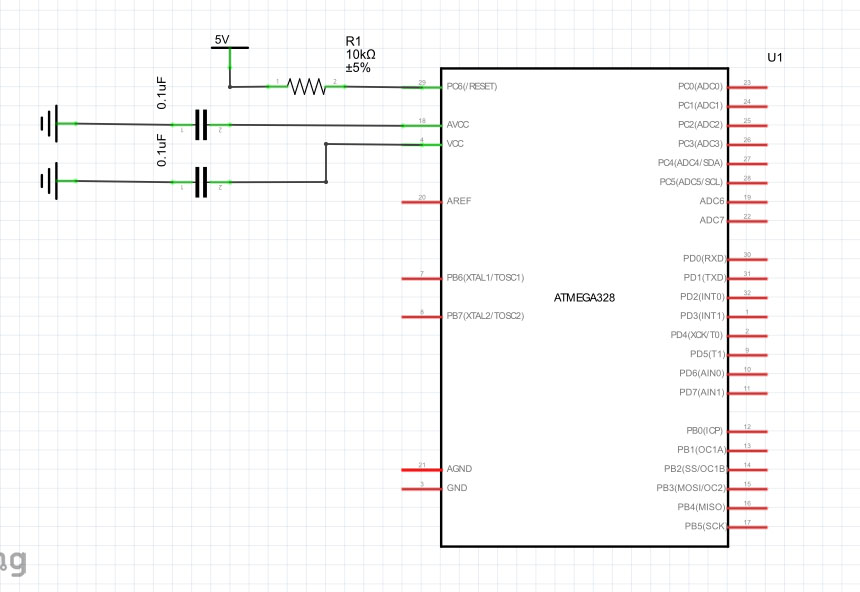
  1. Does an arduino need to have the reset switch? I dont think it does, but just want to make sure.
  2. Is the bare minimum the atmega chip and the crystal with 2 capacitors?

now the more in depth

  1. I want it to have a usb port for charging. I was planning on using a MCP73831 to do this with one cell. The question then comes in, will this affect the timing calculations since the arduino will be running at less than 5V? Does that affect what the millis() returns?

  2. would I be better off using 2 cells and a voltage regulator circuit also to get a steady 5v?

Thanks for your time!

Only if you plan to reprogram in-system.

No.

The amount by which the frequency will vary is highly likely be insignificant for what you are doing.

Doubt it.

I was planning on programming with ICSP at first.. then possibly with a built in FTDI chip.
So if I go with the FTDI, I will need to have the reset button in there?

No, you do not need a reset button. Even if you plan to reprogram in-system. Sorry about the mistake. I read "Does an arduino need to have the reset?"

FTDI interface would have DTR go thru a 0.1uF cap to the Reset pin for a software created reset to start the bootloader. I leave a reset button off a lot of designs - if something needs reset during code development, one can always be connected to reset and Gnd on a header pin.

If are running from internal 8 MHz clock source, then you really just need 10K pullup on reset, and 0.1uF caps on the VCC/AVCC pins.
External 8MHz crystal, then yes 2 caps go with the crystal. Or a resonator with included caps.
At 16 MHz, you need 3.8V to meet all performance specs.
At 8 MHz, can meet all performamnce specs from a 3.7V-4.2V Lipo.
If you're just making a chronograph, 8 MHz from single cell LiPo would be fine.
Add an FTDI header and ICSP header so you can connect either one. Doesn't need to be full size pins on 0.1" pitch, can be smaller ones (like 1.5mm JST connectors) and then use an adapter cable to connect to your programmer and USB/Serial device.
Your chronograph will have some kind of display? Like a little bubble display? I got these little guys from Sparkfun, easy to control with a single MAX7219, or you could do your own multiplexing in software in various ways adding current limit resistors.
http://www.crossroadsfencing.com/BobuinoRev17/

Those are the exact ones I am using, but only one, its just going to display the FPS. I have it wired thru a 74HC595 at the moment.
I went with a atmega 328, since I am most comfortable with that. Is there a smaller cheaper one I can use? Mind you I am planning to use one of those tiny bluetooth modules on it also.
So right off the top of my head it needs to have
7 pins for the display, 4 to the bubble display, and 3 to the 74HC595.
2 pins for bluetooth, send and recieve, if I use a 3rd for reset can you just program the arduino thru that? Or would I still need an ftdi chip on the board?
1 pin for IR led emitters.
2 pins for IR phototransistors.

16 pins total not counting the possibility of using a reset pin.
So is there a better choice of atmel chip to use for this project, that I could run at the 8mghz like you suggested, that has that many pins?

I attached an image, thats all thats needed to do to run on the internal 8mghz oscillator?

32-pin TQFP part - you're missing the other VCC & Gnd pin.

I count 19 plus Reset.
You need MISO, MOSI, SCK, Reset, Vcc. Gnd brought to an ICSP header so you can program the part, or use a breakout cable to access the pins, or an adapter like this that you press down on the part to connect to those 6 pins for programming.
Make sure your other devices do not output on the MISO, MISO, SCK pins; and if they do, make sure their outputs are disabled when the programmer asserts Reset.

7 pins for the display, 4 to the bubble display, and 3 to the 74HC595.

altho I suspect the 7 pins and the '595 output might be the same thing.
So maybe a Attiny2313 or 4313 might work IO wise, if the smaller flash and SRAM size sufficient.

β€’ Data and Non-volatile Program and Data Memories
– 2/4K Bytes of In-System Self Programmable Flash
β€’ Endurance 10,000 Write/Erase Cycles
– 128/256 Bytes In-System Programmable EEPROM
β€’ Endurance: 100,000 Write/Erase Cycles
– 128/256 Bytes Internal SRAM

CrossRoads:
32-pin TQFP part - you're missing the other VCC & Gnd pin.

I count 19 plus Reset.
You need MISO, MOSI, SCK, Reset, Vcc. Gnd brought to an ICSP header so you can program the part, or use a breakout cable to access the pins, or an adapter like this that you press down on the part to connect to those 6 pins for programming.
Make sure your other devices do not output on the MISO, MISO, SCK pins; and if they do, make sure their outputs are disabled when the programmer asserts Reset.

http://www.hobbyking.com/hobbyking/store/__46316__Atmel_Atmega_Socket_Firmware_Flashing_Tool_USA_Warehouse_.html?strSearch=atmega

Yeah, forgot those, but as they have to be there I was only worried about getting the non defaults connected :slight_smile:
I have that exact push on programmer already, awesome!

yeah 7 was the total for running the bubble display, between both it and the 595

CrossRoads:
FTDI interface would have DTR go thru a 0.1uF cap to the Reset pin for a software created reset to start the bootloader. I leave a reset button off a lot of designs - if something needs reset during code development, one can always be connected to reset and Gnd on a header pin.

If are running from internal 8 MHz clock source, then you really just need 10K pullup on reset, and 0.1uF caps on the VCC/AVCC pins.
External 8MHz crystal, then yes 2 caps go with the crystal. Or a resonator with included caps.
At 16 MHz, you need 3.8V to meet all performance specs.
At 8 MHz, can meet all performamnce specs from a 3.7V-4.2V Lipo.
If you're just making a chronograph, 8 MHz from single cell LiPo would be fine.
Add an FTDI header and ICSP header so you can connect either one. Doesn't need to be full size pins on 0.1" pitch, can be smaller ones (like 1.5mm JST connectors) and then use an adapter cable to connect to your programmer and USB/Serial device.
Your chronograph will have some kind of display? Like a little bubble display? I got these little guys from Sparkfun, easy to control with a single MAX7219, or you could do your own multiplexing in software in various ways adding current limit resistors.
Cross Roads Electronics

On the schematic for the ATtiny2313 I dont see VCC/AVCC pins, I just see a VCC pin. Do I just connect that one to a 0.1uF cap then to ground?

Yes. As close as possible to the processor.

The t2313 family does not have an analog-to-digital converter.

I might stay with the 328 for now, I know it, already have the device working, and the attiny2313 is confusing me a little. I'll put a schematic up here when I am done, then maybe try to do one with the ATtiny

Look at page 5 of ATtiny spec - it's an awful lot like a '328P. Both have two 8-bit ports, and part of a 3rd.
Attiny uses 3 pins of the partial PortA for the crystal and Reset, while the '328 uses 2 pins of PortB and 1 pin of partial PortC for those.

As Coding Badly indicates, the only real difference is the lack of an ADC on the Attiny, which you weren't using anyway, so no loss.
So you have 16 IO to use, vs 20 on the 328.
They are less expensive, $1.70 (2313 DIP) and $1.95 (4313) vs $3.70 (328P DIP).
Pricing from Digikey.com

CrossRoads:
Look at page 5 of ATtiny spec - it's an awful lot like a '328P. Both have two 8-bit ports, and part of a 3rd.
Attiny uses 3 pins of the partial PortA for the crystal and Reset, while the '328 uses 2 pins of PortB and 1 pin of partial PortC for those.

As Coding Badly indicates, the only real difference is the lack of an ADC on the Attiny, which you weren't using anyway, so no loss.
So you have 16 IO to use, vs 20 on the 328.
They are less expensive, $1.70 (2313 DIP) and $1.95 (4313) vs $3.70 (328P DIP).
Pricing from Digikey.com

Yeah I dont like to quit, so I was reading more.. and started getting it a bit.
However, I am using analog pins on the arduino. I am using 2 phototransistors right now that just connect to the analog pins 1 and 2 on the arduino. If the 2313 doesnt have analog-to-digital converters, then can I connect them directly to it? do I need to make my own ADC before the phototransistor can connect to the 2313?

Also bear in mind ATtiny processors nearly always have just two timers.

Ok guys, so I worked on this last night and this is what I came up with.
I went with an ATmega168 (in the schematic its a atmega8 since it has the same pinout), cheaper than a 328 but does basically the same for this application.
Charging is accomplished with a MCP73831, the only question I have about this is, does the power for the rest of the board go right to the battery like I have it in the schematic?

PLEASE, I have no real experience with making a schematic.. if you guys approve I will move forward and make the board file, then get a test made :smiley:

chronograph.pdf (21.8 KB)

OOPS forgot one wire on the 74HC595
new schematic

chronograph.pdf (21.8 KB)

Some errors: AD6 and AD7 are analog input only.
SMD processor chip intended? Or 28-pin DIP?
Why two LEDs, D2 & D4? Unless both are Red (Vf ~ 2.2V) only 1 will likely turn on.
Q1, Q2 - what will those be doing - just pull PD6 & PD7 low when enough light shines on them?
(sorry if I missed any earlier descriptions you may have had, just trying to understand).

Power - you have 5V on the wrong side of the caps.
Power goes to the pin, the cap goes from the pin to Gnd.
Each of VCC/AVCC needs a cap.
Most folks use the 6-pin ICSP header, 10 is okay too.
Need a 0.1uF cap across the shift register power & Gnd.
MCP73831, load is off the battery+. Pay attention to Fig 6-4,6-5 when you layout your board.

CrossRoads:
Some errors: AD6 and AD7 are analog input only.
SMD processor chip intended? Or 28-pin DIP?
Why two LEDs, D2 & D4? Unless both are Red (Vf ~ 2.2V) only 1 will likely turn on.
Q1, Q2 - what will those be doing - just pull PD6 & PD7 low when enough light shines on them?
(sorry if I missed any earlier descriptions you may have had, just trying to understand).

Power - you have 5V on the wrong side of the caps.
Power goes to the pin, the cap goes from the pin to Gnd.
Each of VCC/AVCC needs a cap.
Most folks use the 6-pin ICSP header, 10 is okay too.
Need a 0.1uF cap across the shift register power & Gnd.
MCP73831, load is off the battery+. Pay attention to Fig 6-4,6-5 when you layout your board.
http://ww1.microchip.com/downloads/en/DeviceDoc/20001984g.pdf

moved AD6 and AD7 to PD4 and PD5

They are SMD

Changed the names on those LEDs, they are the IR Emitters for the start and end gates on the chrono. I used a LED calculator to figure out the resistor value.

Changed the names on Q1 and Q2, these are the phototransistors. When chrono is ready to go, it turns on the IT emitters, and waits for a break on the analog pins connected to them.

put the power on the right side of the 2 caps I had wrong.. I think I only had 2 backwards.

added a cap on the VCC line that was missing one

changed to the 6pin hearder.. good call.

added cap on power and gnd for the shift register

the nets on the shift register look all crossed over now because I did a temp layout on the board and with them wired this way in the schematic, they are just straight short lines on the board.

Thanks a ton for your help.. im a total hack that just kinda gets thru it like a bull in a china shop.

chronograph2.pdf (22.8 KB)

another quick correction, had ad7 still attached, moved that to pc5

chronograph3.pdf (22.8 KB)