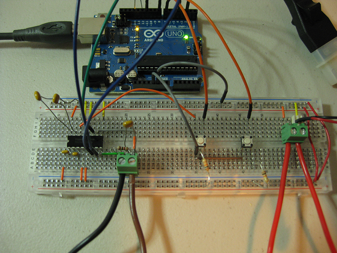
12V motor control with H-Bridge speed issues, plz help

Hello,

I am using a Toshiba TG6549PG H-Bridge to control a 12v DC motor. The reason I went for the TG6549 is because it can handle about 3.5A steady (The motor in it's application would draw around 2.5A).

Here is the datasheet http://www.toshiba.com/taec/components2/Datasheet_Sync/261/3626.pdf

I've run in to the following issues: I have full speed/power in one direction, and very little in the other. The H-Bridge uses four pins, one for standby, one for PWM to control the speed and one for each direction. I have connected the H-Bridge according to the typical application outlined in the datasheet for 12v Vcc, with arduino pins 2 & 4 going to IN1 and IN2, arduino pin ~11 to PWM on the TG6549. I have two buttons, one is for full-speed CW, the other full-speed CCW.

From what I can tell, there is something wrong with my code or the arduino board itself (though I tried it out with an UNO and a MEGA), or maybe the connections yet. I tried the H-Bridge manually, supplying 5V and GND from the arduino and trying the buttons w/ their pulldown resistors directly to the IN1 and IN2 pins, and tied the PWM and SB pins to 5v as well and I get full speed in each direction no problem. That's why I figure its my code... anyways here it is, it's probably a rookie mistake...

//Toshiba TB6549PG Motor Driver Test


//PINOUT
//Input
const int ctrlFwdPin = 7; //0-5v Signal to Arduino Pin 50
const int ctrlRevPin = 8; //0-5v Signal to Arduino Pin 52

//Output
const int fwdSig = 2; //0-5v Signal to in1 pin on Driver
const int revSig = 4; //0-5v Signal to in2 pin on Driver
const int pwmSig = 11; //PWM Signal to PWM pin on Driver
//const int sbSig = 25; //0-5v Signal to SB(Stanby) pin on Driver

//Variables
int ctrlFwdStat = 0;
int ctrlRevStat = 0;

void setup() {

  //Pin Setup 
pinMode(ctrlFwdPin, INPUT);
pinMode(ctrlRevPin, INPUT);
pinMode(fwdSig, OUTPUT);
pinMode(revSig, OUTPUT);
//pinMode(sbSig, OUTPUT);
pinMode(12, OUTPUT); 

}

void loop() {
   
  ctrlFwdStat = digitalRead(ctrlFwdPin);
  ctrlRevStat = digitalRead(ctrlRevPin);

  if(ctrlFwdStat == HIGH) {
     digitalWrite(12, HIGH);
     analogWrite(pwmSig, 255);
     digitalWrite(revSig, LOW);
     digitalWrite(fwdSig, HIGH);
  }
  if(ctrlRevStat == HIGH) {
    digitalWrite(12, HIGH);
    analogWrite(pwmSig, 255);
    digitalWrite(fwdSig, LOW);
    digitalWrite(revSig, HIGH);
  }
  else {
     digitalWrite(12, LOW);
     //digitalWrite(sbSig, HIGH);
     digitalWrite(pwmSig, HIGH);
     digitalWrite(revSig, HIGH);
     digitalWrite(fwdSig, HIGH);
     
  }
}

Right now I have the SB pin tied to 5V and commented it out in my code just to see if that made a difference. The best results I get is if I set IN1 & IN2 high (short stop) in the else() statement and then in the direction that has trouble I get some movement, but not much. It doesn't seem to matter if I give it a PWM signal, it will move proportionally slower. Maybe I have to set the the PWM frequency? (which I have no idea where to start).

Thanks in advance!

A rule of thumb, every output must be set as output during set-up. This pin was never set as output. If you do not set the pin as output it will be floating and will cause erratic results.

const int pwmSig = 11; //PWM Signal to PWM pin on Driver

This part of code is pretty much the same as saying analogwrite 255.

digitalWrite(pwmSig, HIGH);

One other thing, I realize you have been changing and trying things with your code but, you need to have your code commented to help us look for your problems.

Example, what is this pin for?

pinMode(12, OUTPUT);

ooops that was a quick debug its just for an led to light up when the buttons are pressed, to make sure it's not an input problem. One thing I can tell you though is the led is ever so slightly dimmer when I push the button for the direction that piles up.

Example, what is this pin for?

Code:
pinMode(12, OUTPUT);

also I tried setting the PWM pin as an output, but it didn't work. I will leave it on there though.

and are you saying I should use analogWrite(255) instead? the only reason I set the pwm high in the else statement is because the datasheet specifies that the PWM sig should be high when not in use... I guess to keep the capacitors charged? Regardless it didn't make a difference. Other than that does the code make sense?

i guess i'll break out the multimeter tomorrow.

Reading your statement about the led getting dimmer when the button is pressed makes me wonder if your circuits are correct with your buttons. You may want to refer to some of the playground examples and compare them to how you have your circuits built.

Looking at your datasheet at the link you provided, I found you want the "SB" pin low to standby or stop. You can also stop by holding "PWM" pin low.

Using page 6 of the datasheet, I rewrote your code to what I think is correct.

//Toshiba TB6549PG Motor Driver Test


//PINOUT
//Input
const int ctrlFwdPin = 7; //0-5v Signal to Arduino Pin 50
const int ctrlRevPin = 8; //0-5v Signal to Arduino Pin 52

//Output
const int fwdSig = 2; //0-5v Signal to in1 pin on Driver
const int revSig = 4; //0-5v Signal to in2 pin on Driver
const int pwmSig = 11; //PWM Signal to PWM pin on Driver
const int sbSig = 25; //0-5v Signal to SB(Stanby) pin on Driver
const int LED = 12;
//Variables
int ctrlFwdStat = 0;
int ctrlRevStat = 0;

void setup() {

  //Pin Setup 
  pinMode(ctrlFwdPin, INPUT);
  pinMode(ctrlRevPin, INPUT);
  pinMode(fwdSig, OUTPUT);
  pinMode(revSig, OUTPUT);
  pinMode(pwmSig, OUTPUT);
  pinMode(sbSig, OUTPUT);
  pinMode(LED, OUTPUT); 

}

void loop() {

  ctrlFwdStat = digitalRead(ctrlFwdPin); // read the FWD button
  ctrlRevStat = digitalRead(ctrlRevPin); // read the Rev button

    if(ctrlFwdStat == HIGH) // If FWD button is HIGH, run motor forward
  {
    digitalWrite(LED, HIGH);
    digitalWrite(sbSig, HIGH);
    analogWrite(pwmSig, 255);
    digitalWrite(revSig, LOW);
    digitalWrite(fwdSig, HIGH);
  }

  if(ctrlRevStat == HIGH) // If Rev button is HIGH, run motor reverse
  {
    digitalWrite(LED, HIGH);
    digitalWrite(sbSig, HIGH);
    analogWrite(pwmSig, 255);
    digitalWrite(fwdSig, LOW);
    digitalWrite(revSig, HIGH);
  }

  else // stop the motor
  {
    digitalWrite(LED, LOW);
    digitalWrite(sbSig, LOW);
    digitalWrite(pwmSig, 0);
    digitalWrite(revSig, LOW);
    digitalWrite(fwdSig, LOW);

  }
}

Alright here is an eagle schematic of the way I have it hooked up, and a few pictures of my breadboard. I did find that I missed one ground connection (one of the S-GND's) on the LH side of the chip. It didn't make a difference when I hooked it back up (I hope I didn't fry it?).

And I tried all this again with the modified code (thank you), to no avail.

I'm not sure if the buttons are correctly represented in the schematic, anyways, as far as I can tell they are the same configuration as in the digital read and button tutorials. The SB pin is still tied to 5v from the arduino, I'll try it again later with arduino actually controlling SB signal, but I don't see much hope there, as I originally had the arduino doing PWM and SB with the same crummy result.

Cheers!

I could not see much wrong except that your LED does not have a resistor in the schematic. You need at least a 220ohm resistor at 5v. If you are using the on-board LED, it is connected to pin 13, not pin 12.

Since I have not spotted the problem, you could move to step by step testing.

Some tests you could do, connect your motor directly to 12v and check speed in each direction. If the speed is correct in both directions, focus back to your circuit and code.

To test your code in pieces, only use one part such as the REV part with no if statement, just let it run. If that works, put the switch read and "if" test back in and see if it still works.

Have you tried measuring the voltages on the IN1 and IN2 pins when you are trying to run the motor in each direction?

If you swap the connections to IN1 and IN2, is the "bad" button still the same one?

I did these tests:

-first, I commented out the LED from the code, because I know the buttons are working. This made no difference.
-I uncommented/readded control of the SB pin in the code this also did not work

-I then tested the motor right off of a 12V 2.6Ah lead acid battery. The motor spun faster in both directions, though slightly slower in the reverse direction, or at least it made a slower 'sound' in reverse.

-Then I broke out multi meter. Here are the voltages I found:
Supply: 11.90V
Fwd direction output voltage (across motor terminals): 7.86V (shouldn't it be 11.90v?)
Rev direction output voltage (across motor terminals): 21.7mV (uh oh)
Signal to IN1 (fwd): 4.91V
Signal to IN2 (rev): 1.77V (should be 4.5V to 5.5V?)
Signal to SB: 4.91V
Signal to PWM (fwd btn pushed): 4.91V
Signal to PWM (rev btn pushed): 1.88V (uh oh)
Signal to arduino Pin 7 (button pushed): 4.91V
Signal to arduino Pin 8 (button pushed): 4.91V
Supply to buttos: 4.91V

SO there is obviously something causing the Arduino to send a lower voltage when the REV btn is pressed.

Have you tried measuring the voltages on the IN1 and IN2 pins when you are trying to run the motor in each direction?

If you swap the connections to IN1 and IN2, is the "bad" button still the same one?

nope that's one of the first things I did, and I even swapped the buttons. The motor runs nicely in rev with IN1 & IN2 swapped.

now here's another question do these/other H-Bridges normally have a voltage drop like that? I'm expecting 12v or slightly lower output with a 12v supply... or have I got it wrong? The datasheet mentions 1ohm 'on' resistance. I'm assuming that wouldn't yank it down to 7.8V like that...

the other thing is how sensitive are the arduinos to shorts? because I have messed up on a few occasions where the arduino would rest itself could I have wrecked my arduino, or both of them?

It sounds like either the Arduino Vcc supply is dropping when you try to drive the motor in reverse, or the H-bridge chip is loading IN2 and PWM heavily under those conditions. I suggest you measure the following, in each case when the motor is not running, when it is running forwards, and when you try to run it in reverse:

  1. 12v supply

  2. Voltage on the Vreg pin of the H-bridge chip (should be approx 5 volts)

  3. Arduino Vcc

Supply: 12.23v idle
12.02v motor fwd
12.23v motor rev

Vreg Pin: 5.02v idle
5.12v motor fwd
5.02v motor rev

Arduino Vcc (i'm assuming the 5V pin?):
4.93v idle
4.96v motor fwd
4.94v motor rev

One thing though, (i think I mentioned in one of my previous posts) if I cut the arduino out of the equation, tie SB and PWM to 5v, put IN1 and IN2 straight to the buttons and try it works great except for the lower voltage output (8v instead of 12v)

I just spotted an error in your code. The line:

if(ctrlRevStat == HIGH) // If Rev button is HIGH, run motor reverse

should be:

else if(ctrlRevStat == HIGH) // If Rev button is HIGH, run motor reverse

so that exactly 1 of the 3 blocks of code is executed. As the code stands, if you hold down the Fwd button, the first block (forward) and third block (stop) will both be executed each time loop() is called.

well that did it!

now would this application make better use of the switch() case function? that's probably what i'll be using anyway since I need to drive four of these motors...

and lastly, any thoughts on the output of the h-bridge? i'm still only getting 8.6v max. I'm using a 12v battery directly which has improved the smoothness and speed (slightly) of the motor. would I do better with a regulator in the circuit or do I have to increase beyond 12v supply?

• Low ON-resistance: 1.0 ? (up + low/typ.)

The ON-resistance quoted from the data sheet shows 1 to 1.75 ohms. What this means is you will have voltage drop across the H-bridge that will be related to the current draw of the motor.

12v - 8.6v = 3.4v drop Rough math using mid-range ohm rating 3.4v / 1.4 ohms = 2.34 amps going to the motor.

Here's an alternative h-bridge chip that has lower output resistance: http://www.farnell.com/datasheets/1383760.pdf.

A switch statement is not appropriate for that application because you do not have a single input that takes many (more than 2) values. But you can write a function that does the job for one motor, taking the input and output pins as parameters. Then you can call the function once for each motor.

got it. thanks for your help guys!