2x16 LCD with I2C backboard

Hello, I'm trying to get an LCD display to work, in order to print some measurements i take but I'm running into problems.

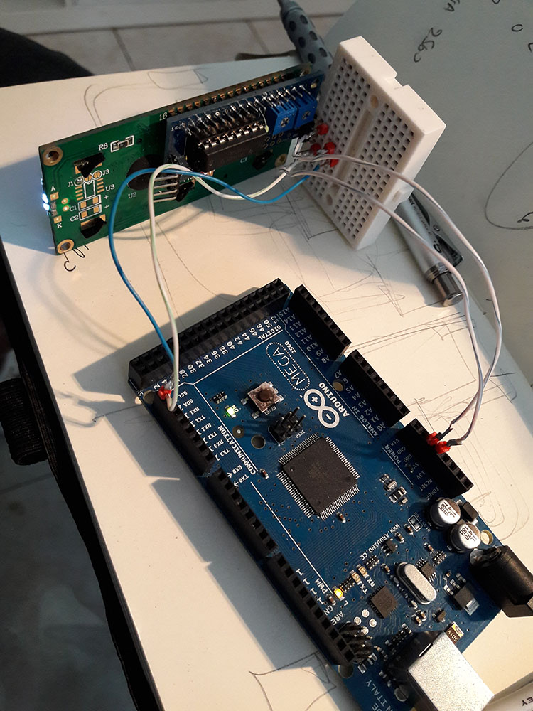
I use an Arduino Mega 2560 board, an LCD display (which i don't know any product number), and a backboard "LCD I2C Breakout board" which uses PCF8574N chip.

My circuit is GND - GND
SDA - pin20 SDA
SCL - pin21 SCL
VCC - 5V

I runned i2c scanner and got 0x20 as an adress which i searched online to found (0x20, 4, 5, 6, 0, 1, 2, 3, 7, NEGATIVE) because the code i used had an adrress like that.

and that is the code

/* Demonstration sketch for PCF8574T I2C LCD Backpack 
Uses library from https://bitbucket.org/fmalpartida/new-liquidcrystal/downloads GNU General Public License, version 3 (GPL-3.0) */
#include <Wire.h>
#include <LCD.h>
#include <LiquidCrystal_I2C.h>

LiquidCrystal_I2C  lcd(0x20, 4, 5, 6, 0, 1, 2, 3, 7, NEGATIVE); // 0x27 is the I2C bus address for an unmodified backpack

void setup()
{
  // activate LCD module
  lcd.begin (16,2); // for 16 x 2 LCD module
  lcd.setBacklightPin(3,POSITIVE);
  lcd.setBacklight(HIGH);
}

void loop()
{
  lcd.home (); // set cursor to 0,0
  lcd.print(" HELLO"); 
  lcd.setCursor (0,1);        // go to start of 2nd line
  lcd.print(millis());
  delay(1000);
  lcd.setBacklight(LOW);      // Backlight off
  delay(250);
  lcd.setBacklight(HIGH);     // Backlight on
  delay(1000);
}

So by using that address i got text instead of bars but only weird characters. So i could really use some help. I have tried many other codes and libraries with no luck. As you may understand i know very little so be patient.

i attach pictures of circuit and LCD, thank you for your time

I've not seen that LCD backpack before.
Do you have a link to where you got it and/or a schematic for the board?
Are there any components on the back of the backpack PCB?
I'm interested in what the 2nd pot is used for.

The PCF8574 requires that the 3 address pin either be strapped high or low since there is no internal pullups/pulldowns on those pins. The PCB looks like they can be jumpered either way but may not provide a default strapping. You need to check this to make sure that they are strapped high or low to set the address that you want.

The i2c address is completely independent of the pin mappings.
The pin mappings in the constructor for that library tell the library how the PCF8574 i/o pins are wired up to the hd44780 pins.
If the pin mappings you tell the library do not exactly match the pin mappings used on your backpack it will not function correctly.
You need to look at your backpack or the schematic for the backpack and make sure that the numbers you enter in to that constructor are for the correct Px pin of the PCF8574 for that LCD function. If any of the eight numbers/pins are incorrect or out of order it will not work.

You could try my hd44780 library package. It will automatically figure out the i2c address and should be able to automatically determine pin mappings.
It also includes a diagnostic sketch that will test the i2c signals and the internal RAM of the hd44780 display.
It can be installed using the IDE library manager and does not require modifying any currently installed libraries.
You can read more about it here: GitHub - duinoWitchery/hd44780: Extensible hd44780 LCD library
The i/o class for backpacks that use the PCF8574 chip is hd44780_I2Cexp and the diag sketch is called I2CexpDiag.

I would recommend installing hd44780 and running the included I2CexpDiag diagnostic sketch.

--- bill

i don't have any more info on the backpack because it was just given to me. i can't unsolder it to look at the back.

i never succeed to print something to the lcd until i tried another code to print my real time sensor data.

/*
Test code for the Arduino Uno
Written by Tom Bonar for testing
Sensors being used for this code are the MB10X0 from MaxBotix
All PW inputs are coded in this for simplicity.
Remove the comments to use the additional sensor inputs
*/

#include <Wire.h>
#include <LCD.h>
#include <LiquidCrystal_I2C.h>

LiquidCrystal_I2C  lcd(0x20, 4, 5, 6, 0, 1, 2, 3, 7, NEGATIVE);

const int pwPin1 = 5;
const int pwPin2 = 9;
//const int pwPin3 = 6;
//const int pwPin4 = 9;
//const int pwPin5 = 10;  // This is the 5th pin that would allow for PW input
//const int pwPin6 = 11;  // This is the 6th pin that would allow for PW intput
const int triggerPin = 1;
long pulse1, pulse2, sensor1, sensor2, inches;

void setup () {
  
  lcd.begin(16, 2);
  lcd.clear();
  
  Serial.begin(115200);
  pinMode(pwPin1, INPUT);
  pinMode(pwPin2, INPUT);
  //pinMode(pwPin3, INPUT);
  //pinMode(pwPin4, INPUT);
  pinMode(triggerPin,OUTPUT);
  //pinMode(pwPin5, INPUT);
  //pinMode(pwPin6, INPUT);
}

void read_sensor(){
  pulse1 = pulseIn(pwPin1, HIGH);
  pulse2 = pulseIn(pwPin2, HIGH);
  //pulse3 = pulseIn(pwPin3, HIGH);
  //pulse4 = pulseIn(pwPin4, HIGH);
  //pulse5 = pulseIn(pwPin5, HIGH);
  //pulse6 = pulseIn(pwPin6, HIGH);
  sensor1 = pulse1/147;
  sensor2 = pulse2/147;
  //sensor3 = pulse3/147;
  //sensor4 = pulse4/147;
  //sensor5 = pulse5/147;
  //sensor6 = pulse6/147;
}

void start_sensor(){
  digitalWrite(triggerPin,HIGH);
  delay(1);
  digitalWrite(triggerPin,LOW);
}

void loop () {
  start_sensor();
  read_sensor();
  delay(100); // This delay time changes by 50 for every sensor in the chain.  For 5 sensors this will be 250

  lcd.setCursor(0,0); // Sets the cursor to col 0 and row 0
  lcd.print("LEFT: "); // Prints Sensor Val: to LCD
  lcd.print(sensor1*25.4*1.26); // Prints value on Potpin1 to LCD
  lcd.setCursor(0,1); // Sets the cursor to col 1 and row 0
  lcd.print("RIGHT: "); // Prints Sensor Val: to LCD
  lcd.print(sensor2*25.4*1.26); // Prints value on Potpin1 to LCD
}

that way it worked just fine.. but i still don't know why.

at that point i have to cycle between different sensors readings on the lcd by pressing a button.
any ideas?

thanks for your time
george

PngGiorgos:
any ideas?

Several, but it is hard to say without looking much closer at the board.
It could be:

  • Loose wires
  • Cold solder joints
  • backpack design Or incorrect/missing components on board)
  • It has no bypass capacitors on it
  • It does not have the PCF8574 Address pins strapped high or low.

I have no idea what the 2nd pot is for or what the 22ohm resistor (I think that is the value as I can't quite make out the colors) is used for (probably additional current limiting for the backlight)

The PCB looks like it has the holes to solder in 3 three pin headers to allow using removable jumpers to set the address but it would be difficult now to solder them in as the PCB is already soldered to the LCD.
I would recommend soldering some jumper wires to the PCB to properly strap the PCF8574 address pins to set the address.
Leaving them floating may cause issues as the data sheet says that you must strap them high or low.

I'd also recommend soldering a bypass cap to the PCB as that is also likely to cause issues.
It looks like you could use the two holes on the right side of the PCB. The ones next to the GND and VCC header pins. I'd solder in a .1 uf in those holes.

Did you run the hd44780 diagnostic sketch?
I'm curious if it can properly auto detect that backpack.

--- bill

so i run your code and i get this


Serial Initialized

I2CexpDiag - i2c LCD i/o expander backpack diagnostic tool

hd44780 lib version: 0.8.3

Reported Arduino Revision: 1.6.7
CPU ARCH: AVR - F_CPU: 16000000

A4: digital pin: 58
A5: digital pin: 59
SDA: digital pin: 20
SCL: digital pin: 21

Checking for required external I2C pull-up on SDA - YES
Checking for required external I2C pull-up on SCL - YES

Scanning i2c bus for devices..
i2c device found at address 0x20
Total I2C devices found: 1

Scanning i2c bus for all lcd displays
LCD at address: 0x20 | config: P65401237L | R/W control: Yes
Total LCD devices found: 1

LCD Display Memory Test
Display: 0
Walking 1s data test: PASSED
Address line test: PASSED

Each working display should be displaying its #, address, and config information
If display is blank, but backlight is on, try adjusting contrast pot
If backlight is off, wait for next test

Blinking backlight test: to verify BL level autodetection
If backlight is mostly off but
you briefly see "BL Off" on display with backlight on,
then the library autodetected incorrect BL level
and the library cannot autoconfigure the device

I am gobsmacked by the missing 100nF capacitor.

I guess that the 2k2 resistors are bus pullups.
The 1k0 pot is a mystery.
The 22R is possibly a series resistor for the Backlight. The LCD shows a 100R already mounted (R8). Some LCDs have 0R mounted and hence need a 22R resistor.

As Bill has suggested, hard-wire the A0, A1, A2 jumpers. Easy enough to solder some plain wire. e.g. all HIGH for 0x27.

@Bill,
I have never seen an adapter with the data bus on P0-P3. All my adapters are wired for data bus on P4-P7. Ah-ha, the DIP-16 package makes P3-P0 easy for DB7-DB4. And P4 easy for EN.

David.

David,
There are several different PCF8574 pin wirings out there. Many Arduino users really struggle with trying to get these backpacks to work, since many don't know how to read schematics or how to trace down the pin connections. Some struggle with even getting the i2c address correct.
This is why I put in so much effort to create the auto detection that is in the hd44780 library.

On the resistor. oops. I meant 220 ohm (Red, Red, Black, Black - Brown).
(somehow the other zero got lost with my typing).
Seems like the the backlight might be a bit dimmer if the LCD has this resistor on it.
But some backlight are way too bright IMO so the added resistor might be nice to lower the intensity.

Maybe the 1k pot is in series with the 220 ohm resistor to allow reducing the backlight current even more?
So 1 pot for backlight brightness and 1 pot for contrast?

PngGiorgos,
I'm assuming that the backlight does not blink when running the diagnostic sketch?

I know there are several different PCF8574 pin wirings out there.

My question was about "what is most common now?"
Are there conventional adapters with data on P0-P3 being manufactured?
The OP's pcb is rather unusual. (and he said it was old)

I doubt if the backlight is connected to the PCF8574. Most LEDs draw too much current.
But hey-ho, there are no capacitors. So anything is possible.

David.

david_prentice:
I know there are several different PCF8574 pin wirings out there.

My question was about "what is most common now?"
Are there conventional adapters with data on P0-P3 being manufactured?
The OP's pcb is rather unusual. (and he said it was old)

I'm not sure about what is most common.
Here is what I've seen:
These use the lower nibble:
mjdkz, GYI2CLCD, backlight level = LOW
LCDXIO (rs and en swapped from above)

These use the upper nibble:
ywrobot, dfrobot, sainsmart, funduino, sunrom, sydz, MH, backlight level=HIGH
lcm1602, backlight level = LOW

and the LCDPLUG uses the lower nibble but that is on a MCP23008 chip.

The two most common mappings I've seen:
rs=0, rw=1, e=2, db4=4, db5=5, db6=6, db7=7, bl=3, active=HIGH
rs=6, rw=5, e=4, db4=0, db5=1, db6=2, db7=3, bl=7, active=LOW

So the mappings for this board is same as the mjkdz backpack which is pretty common.

I doubt if the backlight is connected to the PCF8574. Most LEDs draw too much current.
But hey-ho, there are no capacitors. So anything is possible.

The backlight active state detected by the hd44780 library was LOW, so either it isn't connected or is sinking the backlight to turn it on.
The 16x2 backlights don't draw very much current (I have some that are 2ma) and while the PCF8574 can't drive any current it can sink 25ma which is more than enough for most 16x2 backlights.
And if the 220 resistor is on the backlight, then that should definitely bring the backlight current down to what a PCF8574 could sink even on the hungrier backlights.
In fact in a thread a few weeks ago, I walked a previous person though modifying their backpack to directly control the backlight on a 16x2 display since the original design used a FET which does not allow the hd44780 code to auto detect the backlight level. By sinking the backlight directly, the auto detect code can work and the backlight didn't need more current than the PCF8574 could sink.

Now for the 20x4 LCDs, they typically draw from 50ma and up. I've got some that want 450ma !
Not sure why they draw so much more current than the 16x2 displays. I could understand about 4x but not the 12-20x I'm typically seeing.

--- bill

I have a green 20x4 with 0R mounted for the backlight. It took a lot of current @ 5V (and too bright)
I changed 0R to a 47R. It is a bit dim but readable. i.e. with about 40mA.

Most 16x2 seem to have 100R mounted. This limits to about 20mA.

Backlights on TFTs vary greatly. e.g. 50mA on 2.4". up to 300mA on 3.95". 5" and 7" are often too greedy to use with USB power.

The PCF8574 pin mappings correspond to :
chosen by Software party: rs=0, rw=1, e=2, db4=4, db5=5, db6=6, db7=7, bl=3, active=HIGH
chosen by Hardware party: rs=6, rw=5, e=4, db4=0, db5=1, db6=2, db7=3, bl=7, active=LOW

I had rather assumed that the low-nibble version was no longer made. I had never heard of mjdkz

David.

oops. another typo. :o It is mjkdz and not mjdkz
My fingers are not working very well today.

But from what i've seen on the ebay modules, the "brand" text printed on the backpack doesn't mean much.

Hardware vs Software party?
I'm assuming you meant chosen by a primarily h/w type person vs a s/w type person?
There are good reasons to do either and the host code to run either pin mapping is a wash since you have to shift a nibble either way.

The nice thing about the active high backlights is that they will come on by default before any host code has run since the PCF8574 will power up with the pins in input mode with the pullup enabled which is effectively a HIGH output.
But if you want to allow the device to powerup with the backlight off to save power, then active low can make sense.

--- bill