hello guys,
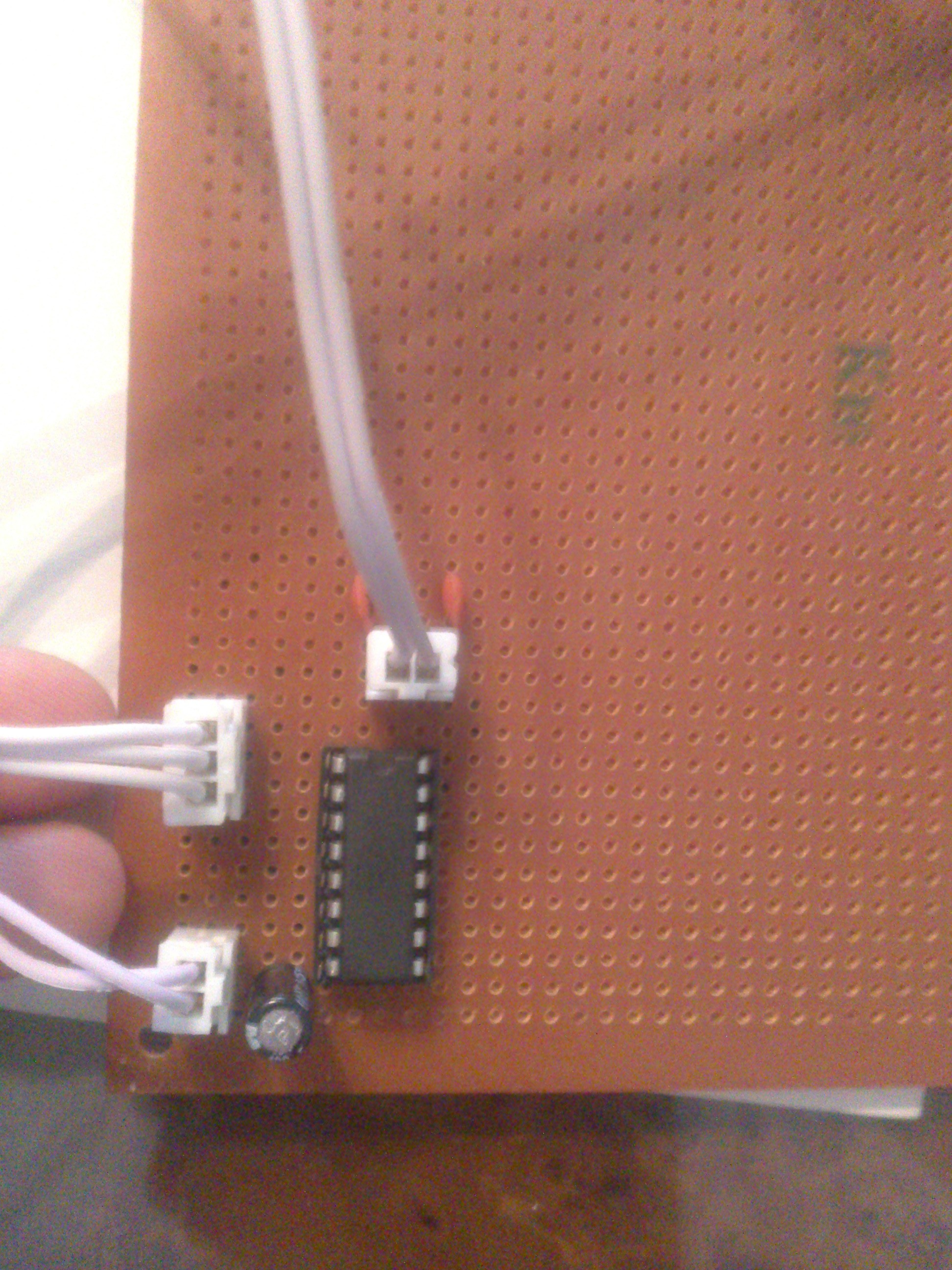
check the attachment file please, this is the circuit i just build for the L293D
i was trying it, it works fine but the IC got overheated :S so what might be a solution for this ? and what's the reason ? is it because of the capacitors or it's just normal ?
i am using a 12V motor of an RC car and feeding the IC with a 12V current from VCC1 connected to 12V + and the pin4 GND connected to - of the 12V
when trying it on breadboard there was no overheating
soldered pins : 1, 2, 3, 4,6,7,8
soldered just to the "PCB" : 9, 16
blank pins : 10 to 15
Sounds like it is supply related.
The next step would be to look at the signals on an oscilloscope but I guess you don't have one.
So you are just shooting in the dark.
Some shots you could make is to see if things improve with the wires as short as possible. Add a series inductor ( as big as you can get ) in line with the high voltage positive supply to the chip.
aha ok this is like your schematic
but now the chip is getting better the heat is supportable not very hot but of course every step for more safety is great
This could be a Diod problem. The diods for a L29x needs to be FAST recovery diodes. If one of them is not fast enought (=fried or faulty) the PWM will produce a backcurrent that is deadly for the L29X. (= get fried because of heat). The process when that this is happening is FAST and results in fire and almost explosion. I have a coule of fried L298N :~
I use 24V to a L298N and when it fries it connect the IN1-4 on L298N with 24V -> Arduini digatal pins. This have fried my Arduino UNO a couple of times. I found a optocoupled L298N on ebay. A bit more expencive but alot cheaer than the Arduino UNO.
cabbagecreek:
This could be a Diod problem. The diods for a L29x needs to be FAST recovery diodes. If one of them is not fast enought (=fried or faulty) the PWM will produce a backcurrent that is deadly for the L29X. (= get fried because of heat). The process when that this is happening is FAST and results in fire and almost explosion. I have a coule of fried L298N :~
I use 24V to a L298N and when it fries it connect the IN1-4 on L298N with 24V -> Arduini digatal pins. This have fried my Arduino UNO a couple of times. I found a optocoupled L298N on ebay. A bit more expencive but alot cheaer than the Arduino UNO.
now it feels better for me when i took the advice of Grumpy Mike, results are better, the IC get hot but not overheated when i use it for a long time
amazing !!
Do you read datasheets ?
The device is supposed to be mounted on at least a copper surface of certain size for heat dissipation.
The datasheet is clear about that, it's shown on top right part of page 1.
A vero board (as you are using) doesn't do this for you, so you have to think of some other way to get it cooled.
Directly next to that on the left side, the datasheet tells you the device can handle 600 mA.
Earlier you were asking about H bridge drivers for over 1 A.
The diodes cannot be incorrect types, because they are integrated and have been so for 27 years.
A device will not last this long if it has such design flaws.
MAS3:
Do you read datasheets ?
The device is supposed to be mounted on at least a copper surface of certain size for heat dissipation.
The datasheet is clear about that, it's shown on top right part of page 1.
A vero board (as you are using) doesn't do this for you, so you have to think of some other way to get it cooled.
Directly next to that on the left side, the datasheet tells you the device can handle 600 mA.
Earlier you were asking about H bridge drivers for over 1 A.
The diodes cannot be incorrect types, because they are integrated and have been so for 27 years.
A device will not last this long if it has such design flaws.
i do read datasheets for sure but i don't understand everything, i mean just the basics
no i didn't say the diodes are not right, i was asking if it is necessary to put more diodes connected to the IC
by the way there is 2 pins which are Ground and heat sink, what do they mean heat sink where do you have to connect that pin to make the chip cool down ?
This is the place where you can attach some metal to help get rid of the heat from the chip. If you have a PCB then you can use a patch of solid PCB track to help cool the chip, or you can clamp an extra piece of metal onto it.
no i didn't say the diodes are not right, i was asking if it is necessary to put more diodes connected to the IC
by the way there is 2 pins which are Ground and heat sink, what do they mean heat sink where do you have to connect that pin to make the chip cool down ?
I didn't react to you about the diodes.
Someone else said this could be a diode problem, but that is very unlikely and i tried to explain this to the both of you.
And no, there's 2 * 2 pins that are labeled GND and Heat sink.
As Grumpy_Mike explained a custom PCB can be made to act as heat sink (within limits).
A vero board can not, because it has no large piece of copper, just a lot of very small pieces.
Therefore a vero board will do a very poor job at this.
This is the place where you can attach some metal to help get rid of the heat from the chip. If you have a PCB then you can use a patch of solid PCB track to help cool the chip, or you can clamp an extra piece of metal onto it.
aha ok so it's either a heat sink (attached to piece of metal) or attached to GND right ? both can take any function of these 2 ?
MAS3:
And no, there's 2 * 2 pins that are labeled GND and Heat sink.
As Grumpy_Mike explained a custom PCB can be made to act as heat sink (within limits).
A vero board can not, because it has no large piece of copper, just a lot of very small pieces.
Therefore a vero board will do a very poor job at this.
and if i attached a piece of metal to it, it won't work 2 ?
if there is no solution for this other than capacitors and inductor as suggested Grumpy Mike then what i can do is to put a temperature sensor which can tell me the temperature so when it gets close to 60 degrees to 70 degrees then a buzzer will make a buzz so i know that i must turn the system off and it will be safe then !!
hey guys, because my projecg is around an rc f1 car so I just noticed that I can use the body of the car to cool the chip down, better than leave it like this, I can put it on one of the sidepods, the chip will be in a perpendiculaire line to the ground, the whole circuit of it will be so do you think this will effect anything any function or the position doesnt matter if we're talking electronics ? because physically the chip we'll be getting the maximum air,,, threw the hole of the sidepod
Are those sidepods functional ?
Very unlikely.
If the body is metal, you can use that for heat dissipation.
But if you connect it directly, then you have GND on the body of your car and need to remind that.
MAS3:
These 4 pins are both GND and heat sink, not either one.
Use all 4 to have a more efficient path to get rid of heat.
Buzzer that makes you turn it off ?
Why not have the Arduino handle this by taking action in case of overheating, it's available right there.
so i connect the 4 pins to GND that's an idea
and about the buzzer, what i mean here is that the buzzer will give you a signal so you know that you must be carefull
and maybe i can put a display that will give me the temperature of the chip captured by the sensor