I purchased an Arduino a few months ago and after doing a few tutorials in my spare time I decided to embark on my project.
Let me first just say that I as an environmental scientist my knowledge of electrical engineering and programming is limited from an educational background, so go easy on me ![]()
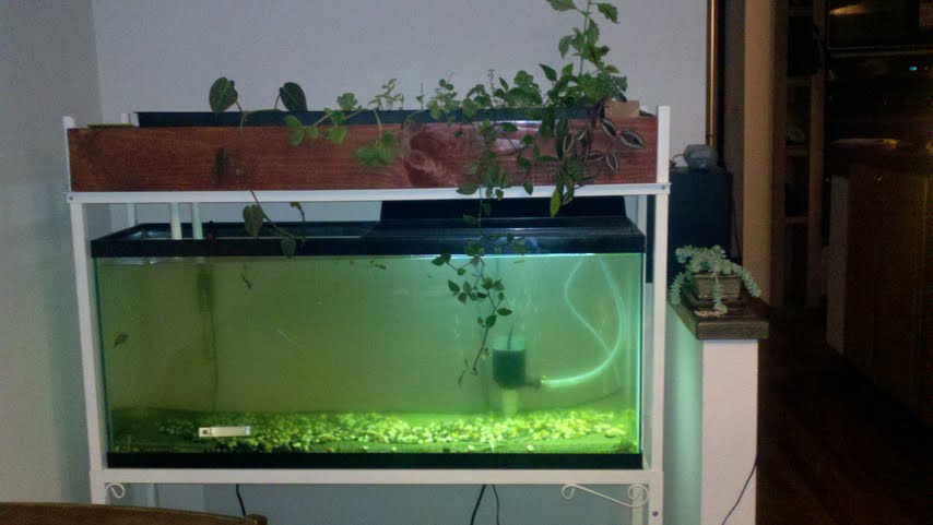
My ultimate goal project involves the integration of Arduino with my aquaponics set up (hydroponics combined with aquaculture), which is also a simultaneous work in progress pictured below: I have broccoli, several types of mint, sugar snaps, 3 species of tropical vines, tomato seedlings, lettuce seedlings, squash seedlings, dill, lemon balm, and a few other herbs and plants with economic value; this is mostly an experiment geared at identifying the fastest and best growing plants in this type of system.
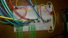
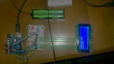
As of now, I have a photoresistor that will later turn on a LED array when it gets dark (in its place there is only one LED to show the code works correctly) I have a temperature sensor, and a LCD screen for displaying data. The LD currently displays "lux" as light units, but I have found a photoresistor is far too unprecise for such a measurement (aside from not being necessary, the lux calculation is a bit cumbersome). I am powering this current setup with the 5V and 3.3V onboard pins of the Arduino.
I have plans to make this setup independent of a power supply, so I have purchased a battery case that currently contains 8 1.2v 2,500mAh rechargable cells (also pictured) for a total of 9.6V in the cell. I have no interest in running the arduino as well on battery power yet (don't want to blow it during my learning curve, already blew some LEDs ^o^ and I know I would need more juice) but I have replaced the 5V and 3.3V sources with the battery into the breadboard. However, when I do so my LCD screen goes white and the circuit does not behave (or work for that matter) as before. My initial thought is that since the output of the cells is highly variable (so says my handy meter) I need a capacitor to make up for times that the current drops below the operational threshold. Is this at all correct. If so what would be the appropriate capacity of this capacitor?
I have posted the code below. It is almost 100% "borrowed" code snippets that I have taken from other projects without copywrite protections. I would greatly appreciate productive criticisms with errors and potential inefficiencies. Thanks in advance for everyone's interest and comments!!!!!
/* ------------------------------------------------------------------------------- */
//PhotoResistor Pin Variables
int lightPin = 1; //the analog pin the photoresistor is connected to
//the photoresistor is not calibrated to any units so
//this is simply a raw sensor value (relative light)
//TMP36 Pin Variables
int sensorPin = 0; //the analog pin the TMP36's Vout (sense) pin is connected to
//the resolution is 10 mV / degree centigrade with a
//500 mV offset to allow for negative temperatures
float temp;
int tempPin = 0;
int ledOut = 9; // LED on Digital Pin 7
int aiValue = 0; // input value
int setPoint = 700; // Trigger value for led out
// LCD Variables
#include <LiquidCrystal.h>
// Connections:
// rs (LCD pin 4) to Arduino pin 12
// rw (LCD pin 5) to Arduino pin 11
// enable (LCD pin 6) to Arduino pin 10
// LCD pin 15 to Arduino pin 13
// LCD pins d4, d5, d6, d7 to Arduino pins 5, 4, 3, 2
LiquidCrystal lcd(12, 11, 10, 5, 4, 3, 2);
int backLight = 13; // pin 13 will control the backlight
void setup()
{
pinMode(backLight, OUTPUT);
digitalWrite(backLight, HIGH); // turn backlight on. Replace 'HIGH' with 'LOW' to turn it off.
lcd.begin(16,2); // columns, rows. use 16,2 for a 16x2 LCD, etc CHANGE TO APPROPRIATE SIZE
lcd.clear(); // start with a blank screen
lcd.setCursor(0,0); // set cursor to column 0, row 0 (the first row)
lcd.print("Temp:"); // change this text to whatever you like. keep it clean.
lcd.setCursor(0,1); // set cursor to column 0, row 1 (the second row)
lcd.print("Lux:"); // Reads "Lux" to show that corresponding reading is light intensity
lcd.setCursor(10,0); // set cursor to column 0, row 0 (the first row)
lcd.print("F"); // change this text to whatever you like. keep it clean.
// if you have a 4 row LCD, uncomment these lines to write to the bottom rows
// and change the lcd.begin() statement above.
//lcd.setCursor(0,2); // set cursor to column 0, row 2
//lcd.print("Row 3");
//lcd.setCursor(0,3); // set cursor to column 0, row 3
//lcd.print("Row 4");
Serial.begin(9600); //Start the serial connection with the computer
//to view the result open the serial monitor
}
void loop()
{
int lightpin = 1; // photoresistor on Analogue Pin 1
//getting the voltage reading from the temperature sensor
int reading = analogRead(sensorPin);
// converting that reading to voltage, for 3.3v arduino use 3.3
float voltage = reading * 5.0;
voltage /= 1024.0;
// now print out the temperature
float temperatureC = (voltage - 0.5) * 100 ; //converting from 10 mv per degree wit 500 mV offset
//to degrees ((volatge - 500mV) times 100)
Serial.print(temperatureC); Serial.println(" degrees C");
// now convert to Fahrenheight
float temperatureF = (temperatureC * 9.0 / 5.0) + 32.0;
Serial.print(temperatureF); Serial.println(" degrees F");
temp = analogRead(tempPin);
temp = temp * 0.48828125;
lcd.setCursor(5,0); // set temp display to column X , row X
lcd.print(temp); // print the temp
int lightLevel = analogRead(lightPin); //Read the // lightlevel
float lightlevel = (lightlevel / 2.0); //adjust the value 0 to 900 to
lightLevel = map(lightLevel, 0, 900, 0, 255); //span 0 to 255
lightLevel = constrain(lightLevel, 0, 255);//make sure the value is betwween 0 and 255
Serial.println(analogRead(lightPin)); //Write the value of the photoresistor to the serial monitor.
lcd.setCursor(4,1); // set Lux display to column 4, row 1.
lcd.print(analogRead(lightPin)); //Write the value of the photoresistor to the LCD screen.
aiValue = analogRead(lightpin); // Read the analogue input value
if (aiValue < setPoint)
{
digitalWrite(ledOut, HIGH); // It has got dark, turn the LED on.
}
else
{
digitalWrite(ledOut, LOW); // It is light again, turn the LED off.
}
delay(1000); //waiting a second
}
/* ------------------------------------------------------------------------------- */