So I use this mosfet to power my 12v fan: http://www.onsemi.com/pub/Collateral/MTP3055VL-D.PDF and I use this circuit: Imgur: The magic of the Internet
Before, when I wrote this in the IDE: pinMode(9, OUTPUT); digitalWrite(9, HIGH); the fan started to rotate really fast as intended and this worked for a couple of days but the mosfet did get hot. But now a few days later when I tried to use it again, the fan only spins a little bit. This issue started appearing after I plugged in a second fan.
Does anyone know why?
What board are you using? Is it a 5V or 3.3 volt board?
If 3.3v, the Mosfet may not be fully turned on. They symptoms are getting hot.

That MOSFET is .1 - .18 Ω @5v, this is a poor choice.
What current does your fan use.
If you didn’t change the wiring, you may have damaged the transistor.
What is the HIGH level on the output pin?
What is the drain voltage when the HIGH is on the gate?
Show us a good image of the wiring.
Either loose wire or you damaged the mosfet.
JohnRob:
What board are you using? Is it a 5V or 3.3 volt board?
I am using a 5v board.
larryd:
What current does your fan use.
In the final setup I want three fans that use 12v and 0.2A.
larryd:
If you didn’t change the wiring, you may have damaged the transistor.
I have not changed the wiring and I tested everything and every wire and component works fine exept for the mosfet.
larryd:
What is the HIGH level on the output pin?
What do you mean with this?
larryd:
What is the drain voltage when the HIGH is on the gate?
That should be 12v.
larryd:
Show us a good image of the wiring.
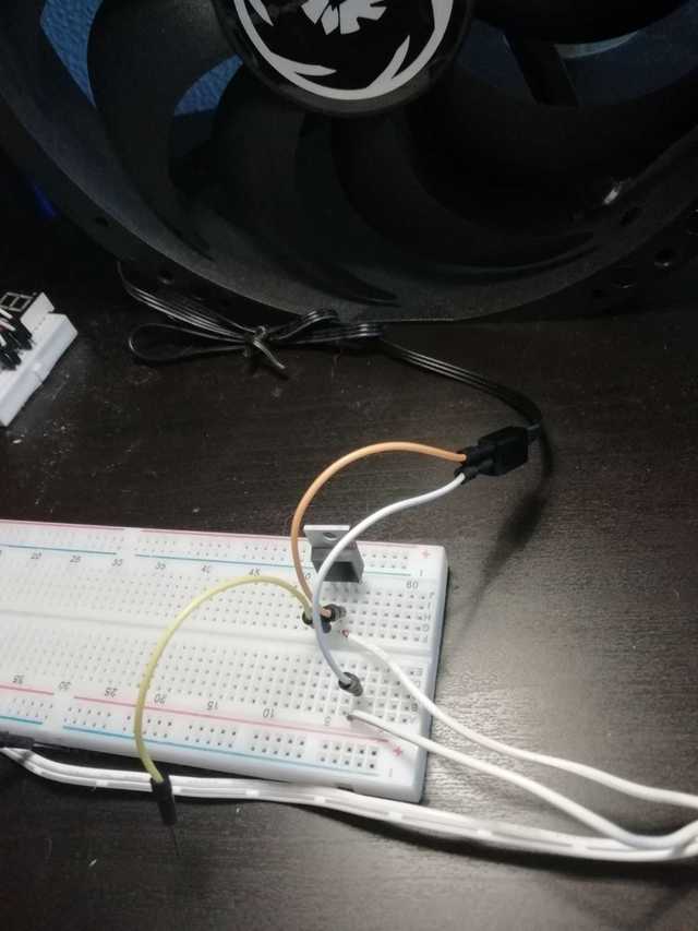
https://imgur.com/a/rCfSvlN
So currently I am using a simple test setup. The 2 white wires coming from the bottom right of the screen are coming from my 12v adapter. The yellow wire is my gate wire which I use to test my mosfet.
DrAzzy:
Either loose wire or you damaged the mosfet.
I definitely don't have any loose wires, especially not now that I am using a small test setup.
Do you guys know what mosfet I'd need in order for me to run three 12v 0.2A fans? Thanks in advance.
You have no freewheel diode across the load. Its an inductive load so requires one to prevent
high voltage spikes damaging the MOSFET, which may be what happened.
Another possibility is that you didn't take full static electricity handling precautions with the MOSFET,
which are extremely delicate until in-circuit (power MOSFETs don't normally have any in-built
static protection circuitry, unless they have a built-in zener (fairly rare)).
And the other possibility is an eBay purchase - counterfeit device.
0.2A at 0.12 ohms on resistance should not be getting remotely warm, let alone hot,
so something was definitely wrong.
0.18 ohms on-resistance is perfectly fine choice for a 0.2A or 0.6A load, BTW, it would be
good upto 1.5 or 2A, then a heatsink or a better device would be needed.
That looks like a 3 wire fan.
Make sure you are using the correct two wires.
What happens when you connect the fan to 12v directly.
The drain to source voltage should be very low (ideally zero) when the Arduino output is HIGH.
You sould measure nearly 5v on the Arduino output when the pin is HIGH.
Cannot see the resistors in you image.
Minor point and not the reason for your trouble, but the 10k resistor is shown on that diagram in the wrong position.
It should be between the Arduino pin and ground, not across the FET gate and ground.

Power MosFET's are pretty tough, hard to damage them. If you did manage to damage the MosFET it would most likely fail ON (i.e nearly a short) which would leave your fan on full. Although obviously I can't be sure but I doubt the MosFET is the root cause. If I had to guess I would first check the battery voltage. if you don't have a voltmeter I suggest you purchase one, even if it is a cheapo one from someplace like Harbor Freight.
I would perform the following tests:
- Connect the fan directly across the batteries and see if it works as you expect (I believe this was suggested previously)
- If the fan is working fine on the batteries, I would remove the gate connection from the arduino and connect it to the battery Plus. The fan should go on as strong as in 1 above.
What's the 220 Ohm resistor for ? I was thinking the battery also.
The gate of the MOSFET looks like a capacitor connected to GND.
This capacitor looks like an instantaneous short when the gate goes from LOW to HIGH, vv.
The 220 Ω resistors limits the Arduino output current when the output goes from LOW to GND, vv.
larryd:
That looks like a 3 wire fan.
Make sure you are using the correct two wires.What happens when you connect the fan to 12v directly.
Cannot see the resistors in you image.
I am using the two correct wires.
If I connect the fan to 12v directly it spins at max speed as intended.
You can't see the resistors since I made a picture of my test setup to show that even in the simplest of circuits the mosfet doesn't work anymore.
JohnRob:
Power MosFET's are pretty tough, hard to damage them. If you did manage to damage the MosFET it would most likely fail ON (i.e nearly a short) which would leave your fan on full. Although obviously I can't be sure but I doubt the MosFET is the root cause. If I had to guess I would first check the battery voltage. if you don't have a voltmeter I suggest you purchase one, even if it is a cheapo one from someplace like Harbor Freight.I would perform the following tests:
- Connect the fan directly across the batteries and see if it works as you expect (I believe this was suggested previously)
- If the fan is working fine on the batteries, I would remove the gate connection from the arduino and connect it to the battery Plus. The fan should go on as strong as in 1 above.
- It works exactly as expected
- This is where it doesn't work anymore and the fan starts spinning really slow
Hi,
Please read the first post in any forum entitled how to use this forum.
http://forum.arduino.cc/index.php/topic,148850.0.html.
It will tell you how to post images that we all can see.
Do you have a DMM?
Thanks.. Tom.. ![]()
- It works exactly as expected
- This is where it doesn't work anymore and the fan starts spinning really slow
Well it sure seems like the MosFET, however I'm surprised as this is not a typical failure mode.
I would suggest one last test then toss the MosFet:
Move the MosFET to a different are of the plug in board. Then retest #2 (Gate to +Vbattery)
Assuming you don't have a spare MosFET and need to purchase one. If you don't get one of the same parts be sure to select one that is identified as a "Logic" type. This means it is compatible with 5V gate drive.
JohnRob:
Power MosFET's are pretty tough, hard to damage them.
I have to differ rather: they can be fragile in all sorts of ways - firstly static damage through handling is
all too easy if you don't take precautions - the gate oxide is extremely thin and most MOSFETs
have no protection circuitry against this - they are more delicate than most logic chips (since
input protection diodes on those are designed to protect against thousands of volts - often logic
devices have an ESD rating in the datasheet)
Gate-oxide punchthrough damage may not disable the device immediately, but cause
leakage currents and poor switching efficiency, leading to sudden unexpected
total failure at a later point.
Secondly if you accidentally short high current through them when switched on the small
Rds(on) can be enough to dissipate enough heat to melt/vaporize the chip in milliseconds -this
is all too common failure for motor drivers that don't have adequate overcurrent shutdown protection.
Typically such failures explode the top of the package off - always wear eye protection working with
live high power electronics...
Switching inductive loads can lead to avalanche breakdown in the MOSFET again causing
extremely rapid heating of the die. Most power MOSFETs have no over-temperature shutdown,
they are just a MOSFET on the die - and it would be hard to arrange anyway as gate drive currents
can be upto an amp or more in larger devices.
And when switching lots of power at higher voltages you have to worry about gate-drain
capacitance feedback causing the gate voltage to exceed safe limits at the switching
transients, and source lead inductance can also produce significant transient voltages between
gate and source - good circuit layout practices should be followed. In short for high power use MOSFETs need significant thought to protection
circuitry to prevent them blowing up.
For low power, low voltage use though MOSFETs are pretty rugged once in circuit and if not subjected
to ESD during handling. One test you can do is measure the gate-source resistance with a DMM - it should
typically be off the scale of the multimeter - if there's a measurable value this could be past ESD damage,
but check the gate leakage current given in the datasheet.
@MarkT ... good idea to measure the gate to source resistance ![]()
@uRThow - ?? I should have asked, when preforming test #2 was the fan off when the gate was not connected to anything?
John
JohnRob:
@uRThow - ?? I should have asked, when preforming test #2 was the fan off when the gate was not connected to anything?
The fan was off when the gate wasn't connected to anything.
JohnRob:
I would suggest one last test then toss the MosFet:Move the MosFET to a different are of the plug in board. Then retest #2 (Gate to +Vbattery)
Assuming you don't have a spare MosFET and need to purchase one. If you don't get one of the same parts be sure to select one that is identified as a "Logic" type. This means it is compatible with 5V gate drive.
I'll test that tomorrow but I don't think that it'll work since I already moved the mosfet when I rebuilt the circuit for the photo. Thanks for the suggestion.
I'll order the same mosfet that I linked in my first post and be more carefull. Is there anything I should keep in mind this time based on the circuit I linked in my initial post?
I have two thoughts:
-
Purchase some spare FETs if funds allow.
-
When you power up the circuit the MosFET should not get warm with one fan. If it does we must have missed something. Also to be really conservative I would connect the gate to the battery when first connect it to the fan.
As I was writing this I had another thought. While I agree MarkT is correct regarding ESD, I've found it really difficult in a lab environment to damage them by ESD alone.
However one consideration might be how they were handled before you received them. These are old obsolete parts so who knows how they were handled before reaching you.