I'm about to start wiring up an 8x8 rgb matrix I've bought from LEDSEE.COM. I've got a few questions before I start, to make sure I'm going about this the right way.
I intend to use 2 TLC5940 ICs to sink the current from the matrix columns (24 pins in total), and then use one 4051 multiplexer to supply V to the matrix rows from the arduino's digital out pins.
4051 can only output up to 25mA. Your row driver needs to be able to supply enough current for every LED in each row, so 24 * If (480mA if you drive each LED at 20mA). You will need some sort of current amplification (FET or Darlington) for the row drivers.
Thanks for the reply ajb - that makes a lot of sense. As the arduino only allows a max current draw of 40mA per I/O pin, it looks like I'll need to amplify current (or supply a secondary pwr supply) in most situations.
The mosfet route looks like it'll be far too expensive.
The datasheet indicates that your matrix can be driven at 30mA per LED at 10% duty cycle which would give you a brighter display, but if you're okay with the brightness at 20mA, then that darlington array will be fine.
Well, I can imagine that it'll take me a while to work out the best multiplexing routines, so there'll be instances when the rows are driven for longer than 10% of the duty cycle. 20mA is probably safer
I've gotten hold of some of the darlington arrays I mentioned above (ULN2803A), but I've just realised that these sink current (providing a common source). Afaik, the TLC5940 sinks current too...
Is there anyway I can use what I've got, or do I need to find a new darlington array?
The FET route seems possible - but as I'd need 8 (one for each common anode), I'm thinking it would be a bit too expensive. Your project looks great - definitely into the idea of not buying the expensive sparkfun kit. I was thinking about using small sections of glue-gun stick as a diffuser -> where did you source yr acrylic from?
I'm going to try and get hold of an allegro UDN2981A which is another 8-channel darlington array - but this time sources current. Hopefully that'll do it.
(I just need to remember that each one of these dense mistakes is teaching me a lesson... freaking annoying none-the-less)
Ah.. I understand now - sorry, I was being a bit dense.
I didn't look at the graph in the datasheet. 120mA max if all 8 channels are on constantly. I'll be using a 100/8 duty cycle, so I'll be able to make use of a higher current.
one thing though - why does the graph stop giving info at 34%?
I'll have a duty cycle of 12.5% - does that mean I can't assume I'll be able to source more than 350mA?
Well, nearly a year later I've come back to this project. I ended up finding a darlington array that can source the current my RGB matrix will require (UDN2981AT).
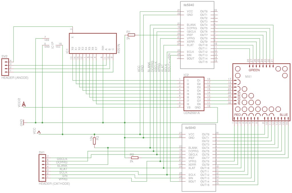
To try help ensure I get the circuit right, I've mocked it up. I'm going to produce it using perf-board.
Understanding this is probably going to be a bit of a headache. I've tried to label everything in the mocked version - if anything's unclear, pls let me know.
One thing I'm unsure of, is whether the 4051 multiplexer is going to be okay to control the darlington array.
Also .. the darlington array is going to have to potentially source a max of (20mA*3)*8 (480mA) on a duty cycle of 12.5%, on one output. The unit is rated for a maximum of 500mA.
I'm not great at reading datasheets -> it seems possible, but if anyone could confirm, would be grateful.
The RGB components of the matrix each have different forward voltage requirements and luminosities.
Green and blue have similar characteristics, red is the odd one out.
Afaik the TLC5940 looks after the current via the setting of the resistor on IREF, will I need to do anything to deal with the differing requirements between R and G/B?
The UDN2981A will source enough current for this LED matrix, but the chip is quite SLOW. If you intend to do fast PWM, you'll see ghost images. The information from row N will 'bleed' to N-1, N-2 etc. You can see this effect in my avatar's icon.
Have a look at the source driver used in the RainbowDuino. Its turn-off time is much more useful.
Can anything be done to improve the speed of a PNP darlington array? Could there be an application circuit, that would give it it a speed boost?
Just asking as I now have the UDN2981s .. but I guess I should look into the M54564P (that the rainbowduino uses).
I read the following note on the datasheet:
Turn-off delay is influenced by load conditions. Systems applications well below the specified output loading may require timing considerations for some designs, i.e., multiplexed displays or when used in combination with sink drivers in a totem pole configuration.
All unused inputs must be connected to ground. Pulldown resistors ([ch8776] 10 k[ch937]) are recommended for inputs that are allowed to float while power is being applied to VS.
Does this mean I should use a pull down to ground on the UDN2981 output pins? Could this maybe help with timing?
The UDN2981A will source enough current for this LED matrix, but the chip is quite SLOW. If you intend to do fast PWM, you'll see ghost images. The information from row N will 'bleed' to N-1, N-2 etc. You can see this effect in my avatar's icon.
What frequency were you using for updating? I'm trying to work out what would constitute fast PWM.
Oh my... I'd have to look at my code. You could do that as well
I was driving the 8x8 matrix with a screen refresh of about 50Hz to 60Hz with 15bit colors (5bit per color). Doing a back of the hand calculation gives 60x8(rows)x32(intensity steps) = 15.4kHz for the row switching. I don't have a scope at hand, so I can't measure it on the real thing ;-(
Anyhow, the turn-off delay for the UDN2981A is something about 5µs, and it was too long for that purpose. The source driver of the R-Duino has a turn-off delay of 1µs, and I haven't seen any ghosting on published images.