We are building up an Arduino compatible with the ATMEGA328 in the TQFP package for the first time. Now we have built two two prototypes and they both seem to be experiencing the same failure. They both worked well to start with. They accepted the boot loader and could be programmed from an FTDI cable. The SD card interface even worked.
Then, after about an hour of running a version of blink (alternating two leds), one LED starts blinking rapidly. It is like it is being reset very quickly.
I can still upload programs via the ISP interface and can swap the initial LED in which case that is the LED that blinks rapidly. I can reinstall the bootloader, but no longer will it accept programs from the FTDI interface.
We have built several boards in using the DIP version of the ATMEGA328 and just copied the schematic for this design. Has anyone else experienced issued using the TQFP?
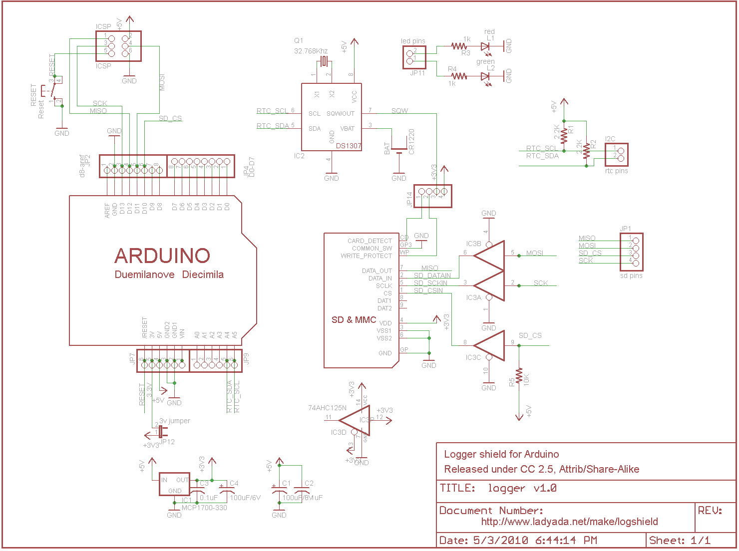
I have uploaded the schematic, and provided a link below.
Thanks,
Justin
i2sd_v1.pdf (43.2 KB)
Something about your MCP1700 regulator at the top right doesn't make sense. You have VCC connected to VIN and VCC connected to VOUT too? What is VCC? Where is it coming from?
You should also have more decoupling capacitors, one for every VCC pin on the ATmega328. You have one on AVCC but that is not enough -- you need one for pins 4/6 as well.
--
The Ruggeduino: compatible with Arduino UNO, 24V operation, all I/O's fused and protected
a sight of the code might be useful?
Wow, you people are fast. Thanks for helping me!
Sorry, but I uploaded the wrong version. I've uploaded the current version here:
Printing Print Schematic.pdf - Google Drive.
Well submit code in next post.
Thanks again!
Justin
MMCP42,
Not sure if this will help, but this is the code that was running fine before the failure.
Thanks,
Justin
void setup(){
  pinMode(2, OUTPUT);
  pinMode(3, OUTPUT);
}
void loop(){
  digitalWrite(3, LOW);
  digitalWrite(2, HIGH);
  delay(1000);
  digitalWrite(3, HIGH);
  digitalWrite(2, LOW);
  delay(1000);

}
Are you sure about those 74LS125 buffers? LS technology needs 5V to work (you're powering it with 3.3V) and it doesn't like input voltages higher than the supply rail (i.e., 5V coming from the ATmega328).
--
The Rugged Circuits Yellowjacket: 802.11 WiFi module with ATmega328P microcontroller, only 1.6" x 1.2", bootloader
No, that schematic uses a 74AHC125. That part can run as low as 2V. A 74LS125 can only run at 5V.
--
The Gadget Shield: accelerometer, RGB LED, IR transmit/receive, speaker, microphone, light sensor, potentiometer, pushbuttons
Thanks @Rugged! I will look into this. It looks like you've pinpointed the problem. I'll let you know.
Thanks again!
Justin
Nice catch @Rugged! I was able to recover the basic MEGA function but not the SD function. I guess I've burned out the LS125A.
I also had a chance to look up your Yellow Jacket Wifi 'diono. Very cool and great price.
Thanks again for the help.
Justin