Hi to all,
currently i have arduino uno with gsm shield working perfectly. I integrated a button (using pin 6 for buttonpin) and when the button is pressed (HIGH) i am making a voice call.
The skech
#include <GSM.h>

#define PINNUMBER ""

// initialize the library instance
GSM gsmAccess; // include a 'true' parameter for debug enabled
GSMVoiceCall vcs;
const int buttonPin = 6;     // the number of the pushbutton pin
const int ledPin =  13;      // the number of the LED pin
int buttonState = 0;         // variable for reading the pushbutton status

void setup()
{
  // initialize the LED pin as an output:
  pinMode(ledPin, OUTPUT);
  // initialize the pushbutton pin as an input:
  pinMode(buttonPin, INPUT);
  // initialize serial communications
  //Serial.begin(9600);

 // Serial.println("SMS Messages Sender");

  // connection state
  boolean notConnected = true;

  // Start GSM shield
  // If your SIM has PIN, pass it as a parameter of begin() in quotes
  while(notConnected)
  {
    if(gsmAccess.begin(PINNUMBER)==GSM_READY)
      notConnected = false;
    else
    {
      Serial.println("Not connected");
      delay(1000);
    }
  }
 // Turn 13 pin led - READY ON
     digitalWrite(ledPin, HIGH);

 // Serial.println("GSM initialized");
}

void loop()
{
   buttonState = digitalRead(buttonPin);
if (buttonState == HIGH) {
    // turn LED on:

  if(vcs.voiceCall("MY_number_stays_here"))
        {
          // Turn Free LED OFF]
          digitalWrite(ledPin, LOW);

          //Serial.println("Call Established. Enter line to end");
          // Wait for some input from the line
          while(vcs.getvoiceCallStatus()==TALKING);
          // And hang up
          vcs.hangCall();
        }
        // TURN FREE LED ON AGAIN after call finished
                  digitalWrite(ledPin, HIGH);

       // Serial.println("Call Finished");
  }
  }
My question is can i use LCD display and connect (wire) the pins as shown Here , but to connect directly on top of the GSM shield not at the arduino as shown in the picture.
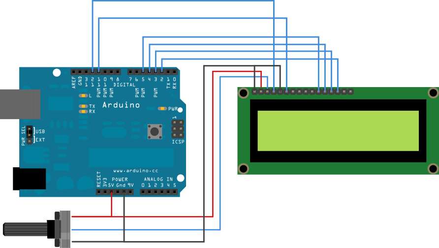
As i see now i am using pins 3,6,5V and GND and in this picture - to connect LCD we have noting to do with pins 3 and 6 , so can i be sure that there will not be a problem??....short circuit , using same pin..or something like that?
Thanks