Random i2c errors, need help to stomp them out please!

I've almost completed my project :fearful:

I have one big problem to take take of:

Random i2c errors!

Sometimes I get them after 30 hours, sometimes after 40 minutes. Usually when a Wire.endTransmission() is happening.

After researching the forum I was sure Grumpy_Mike would come in here, insult my intelligence, and then tell me to decouple. (because he is so grumpy!)

I have been kind enough to save him the trouble! I have pre-insulted myself before posting this and will order a bunch of 100uF/25V capacitors.

But I'm not sure how many to put and where?

Guessing the minimum is 2 capacitors at the power supply?

The capacitors are inexpensive, I don't mind putting in many if it will help. I can put them at the power supply, before the RTC, in and out of Arduino, etc.

I also don't mind the idea of adding another power supply dedicated just to the stepper motor and/or Arduino. Wrapping cables in aluminum foil. Whatever makes the signal reliable.

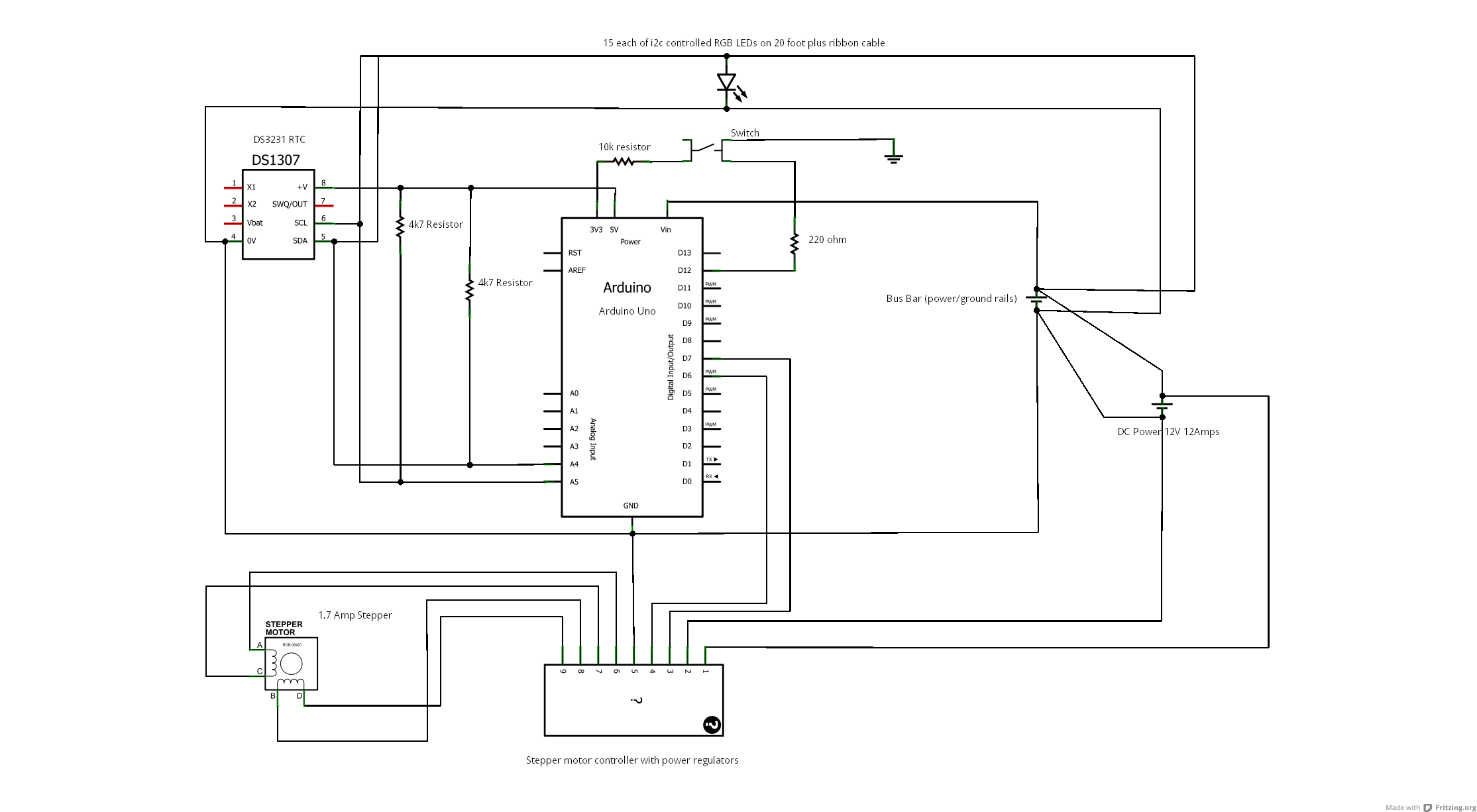
Below is the schematic.

Thanks for any help : )

I think your 15-each I2C-controlled LED's on a super-long ribbon cable might be a problem. First I'd try reducing the 4.7k pullup resistors on the I2C lines down to 1.5k. With that many devices on the bus the capacitance is fairly high and resistors need to be more aggressive to keep rising edges sharp.

Decoupling capacitors only go across the power supplies, not at the Arduino inputs/outputs. Put the capacitor as close to the Arduino pins as possible.

--
The Gadget Shield: accelerometer, RGB LED, IR transmit/receive, speaker, microphone, light sensor, potentiometer, pushbuttons

How do the errors manifest themselves?
De coupling caps are usually 0.1uF (100nF), put them across the VCC & GND pins of your devices.

RuggedCircuits:
Decoupling capacitors only go across the power supplies, not at the Arduino inputs/outputs. Put the capacitor as close to the Arduino pins as possible.

Thanks for the help!

I'm using the barrel jack on the Arduino for power. So should I cut off the head and put it in the VIN and GND with a capacitor? Is the 100uF/25V capacitor ok?

Does it hurt to put them at the power supply as well? The power supply has 2 outputs. One going to the stepper motor controller, the other to the Arduino and lights.

"How do the errors manifest themselves?"

Everything will freeze when a transmission is made to the RTC or LEDs. Usually when a Wire.endTransmission() is happening. As I said this freeze is random. Can happen in 40 minutes, or 30 hours.

So adding a separate power supply just for the motor or Arduino/LEDS won't help?

I was thinking of putting capacitors between each IC as Grumpy_Mike has recommended to some others. Like a cap between the power and Arduino, and another between the Arduino and RTC.

Adding a cap across pins 4 & 8 of the RTC could help, and similarly across VCC & GND of the other I2C devices.

How are the 2 grounds from the 2 power supply outlets connected together?

The RTC is the only i2c item that gets power from the Arduino. All the LEDs on the ribbon cable are powered directly at the lights through separate power input. The voltage is not connected to the ribbon cable.

To confirm, you recommend a 0.1uF (100nF) cap between the Arduino and RTC?

Should I also cut the head off the Arduino barrel jack, connect a cap (what spec?) and run it into Vin and Gnd?

Can I still put 2 100uF/25V caps at the power supply? I worry about the motor causing noise in the signal.

The power supply I thought grounded both outputs automatically to each other? If not I thought the GND connection from the Arduino to the stepper motor control would connect the grounds.

Should I put a cable at the power supply to connect the grounds of both outputs?

Again, thanks for your attention to my problem : )

See the caps near the ICs here? One side connects to a devices +5V pin, the other to ground, right at each device. That is what we are talking about.

Get those added to start, I have to run, will address the rest later.

It's odd that it fails on the Wire.endTransmission. That shouldn't fail in the sense of going into a loop. Do you check the return code from endTransmission? If it is not zero, what do you do? A decoupling (0.1 uF) capacitor between +5V and GND right at the clock might help.

If you don't check the return code you may get bogus data back from the clock. What happens then?

Also, do you have the clock battery connected? It isn't shown on the circuit. I have read the clocks can fail without the battery.

I don't think it's odd that it's getting errors. I found many posts here of people with similar problems. It seems i2c was made for chip to chip communication and not for long cable runs : )

Apparently the line conditions must be perfect or else freezes can occur. It doesn't go into a loop, it just stops the Arduino and won't continue the rest of the code.

I never checked the return code for the wire transmission. I just have error checking code that makes the Arduino grab the time from the RTC again if un-clock like code is found. (time doesn't go backwards, or skip, etc.)

I've put some code in now to print the end transmission result. But many of my transmissions are LED instructions, not just RTC. I've seen the Arduino hang on i2c LED transmissions as well as RTC transmissions.

Yes, the clock battery has always been connected. I didn't put it in the diagram because it is part of the entire RTC breakout board.

Thank you for helping me : )

How do you know the problem is in the I2C endTransmission, and not somewhere else?

I'm curious. What is your project?

I take it that your switching speeds on the i2c cable are not very fast. Is that true?

How do you know the problem is in the I2C endTransmission, and not somewhere else?

I put a lot of Serial.print() lines in my code. Everything works before the Wire.endTransmission() line, but it never comes out of the Wire.endTransmission() line when there is a freeze. The Arduino is just stuck there.

I'm curious. What is your project?
I take it that your switching speeds on the i2c cable are not very fast. Is that true?

It's an artistic clock. I'm not sure what you mean by switching speeds. If you mean how often am I sending i2c communications, then it varies. But it is not a non stop stream of commands. I tried to put as many delays in between communications as possible. I could put more in. But for example it has frozen after a 30 second delay. I put the big delay in just to make sure everything was quiet when the transmission was sent =(

SparksAlot:
I'm not sure what you mean by switching speeds. If you mean how often am I sending i2c communications, then it varies. But it is not a non stop stream of commands. I tried to put as many delays in between communications as possible. I could put more in. But for example it has frozen after a 30 second delay. I put the big delay in just to make sure everything was quiet when the transmission was sent =(

I was just wondering if your data rate was slow enough to use a slower i2c clock. But I'm not sure what clock speed the Wire library uses, or how to change it. So that idea is probably not going to work.

It's not surprising that the problem comes up with the Wire.endTransmission command. The Wire.send commands just put the data in a buffer. The Wire.endTransmission command actually sends it. It does seem like your 20-foot cable is causing the occasional problem.

Perhaps it's time to incorporate an I2C extender into your design. http://ics.nxp.com/products/i2chubs/#Introduction . I'm guessing that if put a scope on the signals they will look like crap!

How about posting some code? The endTransmission shouldn't go into a loop for no reason. Looking at the code there are two places where it loops. Otherwise, no matter how bad the state of the lines, the code should exit. It might do bad things, but it should exit. These are the two places:

 // wait until twi is ready, become master transmitter
  while(TWI_READY != twi_state){
    continue;
  }

... and ...

  // wait for write operation to complete
  while(wait && (TWI_MTX == twi_state)){
    continue;
  }

Both of these are interrupt driven. That is, twi_state is a volatile variable that gets changed by an interrupt. So the first question is, are you fiddling with interrupts? Like disabling them from time to time?

If not, then it is possible that some "event" the hardware is looking for (like the SCL line going high/low) is being missed due to line noise.

What you could consider is a "watchdog timer". That is, every couple of seconds a watchdog interrupt fires, and drags the program back into the main loop. Since you have an onboard clock anyway you could work out from that what you need to do next.

Did you try the suggestion of lower pull-up resistors? Over a long cable run the wire resistance might be so great that what should be a nice square wave at the LEDs is turning into a wishy-washy round signal that they are having trouble interpreting.

Those last 2 posts really gave me a lot to look into :fearful:

Perhaps it's time to incorporate an I2C extender into your design. http://ics.nxp.com/products/i2chubs/#Introduction . I'm guessing that if put a scope on the signals they will look like crap!

I would agree. I think the issue is a bad signal.

There was an excellent document on that site:

http://ics.nxp.com/literature/presentations/interface/pdf/debug.i2c.oscilloscope.pdf

People interested in i2c should give it a look.

A wild guess at my freezing problem would be this quote:

The SDA line is stuck low because the slave is stuck in the transmitter mode

So an I2C extender really seems like it would solve my problem. But I couldn't find a product I can just start using : (

Can you recommend a product? An I2C extender breakout board for example?

So the first question is, are you fiddling with interrupts? Like disabling them from time to time?

Nope.

What you could consider is a "watchdog timer".

Researching a bit shows that to be very tricky. Maybe too tricky for me. Unless there is an easy way to do it without a risk of locking up your Arduino or having to create custom bootloaders.

Did you try the suggestion of lower pull-up resistors?

I did. I didn't have 1.5k as suggested, but I did try 2.2k and noticed no difference in stability. I will try 1.5k when I get my hands on them.

I'm considering replacing the ribbon cable with a cat 5 between the lights in case that helps keep noise out. Are there any off the shelf adapters with a cat 5 female on one side and a 0.1" 4 or more input female on the other? Or would making 15 patch points add just as much instability?

Also, would putting decoupling capacitors on clock and gnd and data and gnd between each light do anything? Or would that destroy the signal instead of stabilize it?

Thanks for all your help!

Another interesting quote from the set of slides you found:

Problem: Due to the bus 400 pF
maximum capacitive load limit,
sending commands over wire (80
pF/m) long distances is hard to
achieve

That suggests that cables should be shorter than about 15 feet.

Ribbon cable is especially bad. Due both to capacitance and cross-talk, ribbon cable is not recommended for lengths over about 10 feet.

Any way to reduce the i2c clock speed? A slower signal should give better performance.

[quote author=Nick Gammon link=topic=55243.msg397325#msg397325 date=1300216206]
The endTransmission shouldn't go into a loop for no reason ....[/quote]

Quite the contrary, endTransmission is typically where the wire library freezes when there are bus issues. It sits in a loop waiting for the bus to become ready and this may never happen in some circumstances. A reset of the I2C sub-module (or the microcontroller) is often required to recover from this. Sometimes this involves resetting all I2C nodes as you never know which node holds the bus in error.

The fact that it freezes the Arduino is a library issue and ideally it should never happen irrespective of bus issues. It is also the case however that it will probably never be an issue if there are no hardware/bus related hickups.

One way to approach this is to fix the wire library. The following link offers some details on how this can be accomplished.

http://www.arduino.cc/cgi-bin/yabb2/YaBB.pl?num=1283887406

SparksAlot:

What you could consider is a "watchdog timer".

Researching a bit shows that to be very tricky. Maybe too tricky for me. Unless there is an easy way to do it without a risk of locking up your Arduino or having to create custom bootloaders.

It's not tricky. No custom bootloaders needed. This example demonstrates:

#include <avr/wdt.h>

void setup ()
{
  Serial.begin (9600);
  wdt_enable(WDTO_1S);  // reset after one second, if no "pat the dog" received
 }  // end of setup

void loop ()
{
  
Serial.println ("Entered loop ...");

Serial.println ("Point A");
delay (500);
Serial.println ("Point B");
delay (500);

wdt_reset();  // give me another second to do stuff (pat the dog)

Serial.println ("Point C");
delay (500);
Serial.println ("Point D");
delay (500);

while (true) ;   // oops, went into a loop
    
}  // end of loop

This resets the Arduino after 1 second. If you are doing something like flashing LEDs then the occasional pause while it regroups for part of a second won't be too bad.

In the example as shown, you see points A do D printed. Take out the wdt_reset() and it only does A to C (which takes one second).

So you just need the enable in setup, and do a wdt_reset() in the main loop. That way if an I2C communication hangs the program simply restarts automatically.

BenF:
One way to approach this is to fix the wire library.

It went into a loop for a reason. The reason was no interrupt received. But I agree that the suggested fix of adding a timeout would be one way out of it. Still, if you are going to timeout in the middle, and maybe reset the I2C hardware anyway, then the watchdog timer would effectively do that anyway.

It looks like the watchdog timer only has a range of 1-8 seconds?

Is there a way to get more time? I would prefer 3-4 minutes.

I need big lengths of time in my code for motor movements for example. There are many long delays in my code longer than 8 seconds. Plus many little ones that add up.

Would prefer not to bust up my code into little 8 second chunks if possible.

I put in one decoupling capacitor and the 1.5k resistors. It did seem to help, but still get freezing. Just after longer periods :~

I put in the decoupling capacitor before the RTC but after the pull up resistors. Can I put another capacitor before the pull up resistors? That would seem to give a clean signal to the i2c clock and data lines maybe?

Can I put as many capacitors as I like all over? Or are there problems in doing so?

To ask again, would putting decoupling capacitors on clock and gnd and data and gnd between each light do anything? Or would that destroy the signal instead of stabilize it?

And again, does anyone know where to buy an i2c extender breakout board?

Thanks : )