Arduino Pro Mini - Problem uploading to board

Hi everyone,

I have a new Arduino Pro Mini 328 3.3v, the only thing i have done to it is to solder header pins so that i can plug it onto a breadboard and also to connect a basic FTDI for uploading.

I downloaded the arduino 0022 on my Mac and tried to upload the blink example but all i got was the error message avrdude: stk500_recv(): programmer is not responding, twice.

I made sure that I selected the right board and serial port (for me it was /dev/tty.usbserial-A600eJSK).

I pressed the reset button (the green LED blinked once) before clicking the upload button. Then the TX on the FTDI board blinked a few times and the green LED on the Mini blinked twice. Then nothing happens for a few seconds followed by the error message.

Gone through the troubleshooting guide and couldn't figure out what I may have missed.

Would appreciate any help.

Cheers

Pass or fail?
http://arduino.cc/forum/index.php/topic,73748.0.html

Hi there,

Thanks for the link. I have tried the loop-back test and it passed.

So could you kindly advise what I could do next?

Thanks again!

Load a simple sketch. Click upload (or press Ctrl + U). The moment the IDE displays the size in the status window, click the reset button.

Nope didn't work. Used the BareMinimum example. Had the same error message - "avrdude: stk500_recv(): programmer is not responding".

I tried pressing the reset button before uploading too and it also didn't work.

Any other suggestions?

Three things,

Could you post a clear picture of how you have things connected?

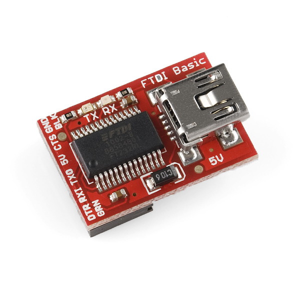
Also, the reset timing on the pro-mini is tighter than the mini v4 since it allows for auto reset. This is done by connecting the GRN pin to the DTR signal on your usb to serial cable/device.

If this does not work, take a ohm meter and check the TXD and RXD traces back to the chip.

Hi BillO,

Thanks for your reply.

I have tried to set things up according to this sparkfun tutorial: Using the Arduino Pro Mini 3.3V - SparkFun Learn

and an image of my setup:
http://dl.dropbox.com/u/33252692/arduinopromini.JPG

Looks like the solder joints on the upper-left corner need a little work. Do you have a multimeter so you can troubleshoot those connections?

the soldering for the right angle headers is actually on the other side.

My apologies. It looks like the solder joints on the upper-right corner (GND, RST, RXI, TXC) need a little work.

ah ok. but i used them for the loop-back test - i plugged wires on my breadboard to connect RST & GND and RXI & TXC; it did work.

When you try to upload without pressing the reset button, does the green LED on the Mini blink?

Yes. After the upload button is clicked, the green LED on the Mini blinks twice, then the TX on the FTDI board blinks twice while the green LED on the Mini blinks once more, followed by another blink on the FTDI TX, and comes the error messages.

Which board do you have selected on the Tools menu?

Pro Mini (3.3V, 8MHz) w ATMega 328

Well, I'm stumped. You've proven that everything works up to the processor. As far as I can tell, the processor is the only left that could be the problem.

Are you certain it is an ATmega328 processor? (I can't tell from the image.)

Are you using the 3V FTDI?

If the 5V FTDI were used, would that bung things up?

(They look a lot alike, they pin-out alike, but they have "3V" / "5V" printed near the USB conn.)

Adding links --


Hey CB, yeah the chip says ATMEL mega 328p.

and

runaway_pancake, it is a 3.3v Ftdi

It's my understanding that there are differences between the Mac USB ports (current limit). Have you tried a different USB port?

hey.. there might be a problem wth burning of bool loader.. i am having similar problem with my Arduino Duemilanove..