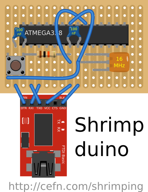
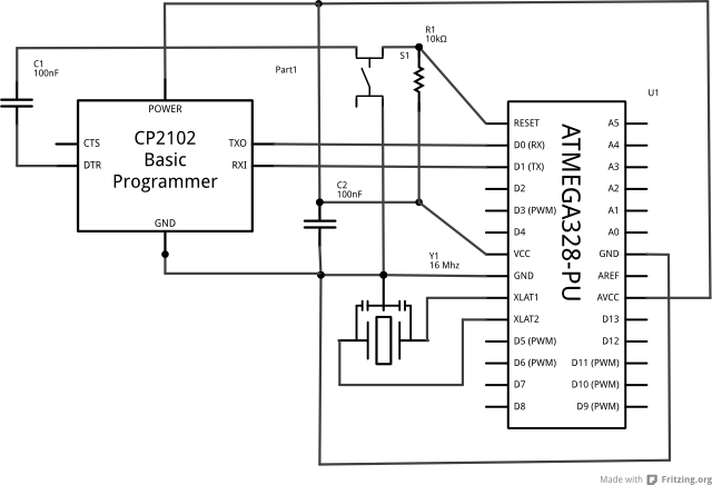
I've been experimenting with a minimal-bill-of-materials USB-connected Arduino Compatible, which currently looks like the attached, (Fritzing diagram off the top of my head, hopefully no errors). We're using Chinese CP2102 boards in the place of the FTDI ones, and ATMEGA328-PUs from Mouser in the place of the full fledged ATMEGA328P-PUs Pico-Power chips. At the moment it looks like we can churn these out for about £3.05 in parts, including built-in USB connectivity.
The configuration seems to work, but I thought others with more experience might be able to warn me in advance of the issues I'm likely to hit when workshopping with people using such a stripped-down board, an alternative USB to TTL and no Picopower.
We have a bunch of official Arduinos which will be used for learning and prototyping, but when people want to build their own circuits and take them away as part of their Shrimped laptops, we'll walk them through a breadboard version of their circuit and then take away the £4 version on stripboard (identically laid out).
For an idea of what a shrimped laptop looks like, take a look at this video of an 11 year old Compaq Presario 700, running Lubuntu, and with some bespoke Python and Arduino code which wires the soundcard through Gstreamer into some HL1606 strips.
The aim is to run workshops where local kids in Morecambe get a freecycle laptop, then shrimp them to something personalised and desirable using linux, recycled bits, toys etc. Then they can take it home and use it as a hacking machine, something like the logic of the Raspberry PI, but using old lappies instead. Hence the importance of low cost for these 'kits'.
Welcome your observations on the Shrimpduino and anything else about the workshopping approach so we're as prepared as we can be for the first ones to be a success.
I missed out the ground wire to the reset button too
I've attached a more accurate diagram to reflect your change and the ground wire, with extra information on the resistors, capacitors and resonator and a layout which still leaves room for female headers if people need them for any reason, although you can compress this layout to lose extra lines if necessary in various ways, depending on the physical size of things like the button.
I did wonder whether wiring to ARef was an 'override' of the default voltage and whether GND just made its way through the chip internally. For Analog input sketches (which I haven't tried yet with this board) I would have had a nasty surprise.
I'm not sure what you're saying about Arduino D14-19 (which is I think the alter-ego of the Analog pins). Are you saying I can at least use them as digitals without ATMEGA PINs 20/21/22 being connected, or is there an interaction with the Analog reference pins even then?
So far I haven't needed to modify the signature information within the IDE to program these chips. I have seen similar instructions when you need to flash the chips, but once the bootloader's on there (I use Optiloader for this), it seems to behave fairly well just treating it as an Uno. Maybe I will uncover some nastiness later when I start using different parts of the board because the signature's wrong. I'll keep an eye out and I have your instructions to follow up on just in case there are weird results.
Thanks for all the suggestions so far, everyone. Really valuable.
CrossRoads:
Will you have any connections to 20/21/22, Avcc/Aref/Agnd, to support analog functions, or to use D14-D19?
AVCC and AGND are required for the processor to function correctly. I vaguely recall that a bypass capacitor is recommended. AREF can be left unconnected.
This is how I start every project I do with a '328.
I often leave off the Power LED.
Crystal & caps you're replaced with resonator, that's fine.
0.1uF/100nF cap are essential for Vcc, Avcc, and Aref if you want to use the internal ADC and get good results.
100uF, maybe get by with another 0.1uF if you have power coming in via CP2102 so its fairly clean.
IO, connect up what need.
Thanks for the diagram, CrossRoads. Really useful for discussion.
Although the two caps on the power lines look like they're in parallel (equivalent to a larger capacitor), I guess the main thing is that they are near the respective pins, hence they are actually doing a different job.
Is it reasonable to squash them into a single cap, assuming that cap is on the path between the pins and the power source. I'm thinking to just run some lines over the top of the ATMEGA from VCC and GND to connect AVCC and AGND, given that VCC and GND are already 'protected' from source variation by a decoupling capacitor. I'm aiming at the fewer tracks and complexity the better, but don't want to make unacceptable/idiot compromises.
I was a bit confused by the line starting...
"100uF, maybe get by with"
...as I didn't know what part of the circuit it referred to. I wonder if some words went missing on this line when posting.
so whats the point of "shrimping" ones laptop? does the arduino interact with the OS or is it basically just powered from the laptop and used to do fun looking things?
I definately agree with helping kids to learn how to do electrical wizardry, and freecycle is a good place to start for those who are hard up, i wish the had it in Spain,
Ideally, the laptop's OS is indeed interacting with the Shrimpduino, although some might just use the laptop to do the programming and experimentation to build standalone devices. Examples of behaviours actively combining the laptop and the arduino which could be fun for different people...
Animation using 5 frames of a scanimation with replaceable printouts - a servo moving the transparency an exact amount to create a zero energy display of something - you have mail, days since last checked facebook, tomorrow's weather, an animal motion (Moire animated illusion like - YouTube)
System which skips tracks when you throw something at the laptop, or similar designed interaction (accelerometer + Rhythmbox/MPD)
LCD which displays the current score from Court One at wimbledon (a friend of mine is obsessed with this and can't stop checking her phone)
Servo-actuated Popup-book mechanisms which trigger, for example, a spider with red LED eyes to leap from behind the screen when someone touches trackpad/keyboard (a donor's kids are threatening to come along and build this one)
Proximity detection system which unlocks the laptop when you walk away from it using ultrasonics to judge your presence
Keylogger which causes every key typed to be illuminated as a single letter on the back of the laptop [logkeys + HL1606] (using the LED array demonstrated in the video in the first post)
Etch-a-sketch dials for painfully-complicated vector authoring in GIMP
System requiring you to elevate your heartrate every 2 hours, else locks the desktop
Dedicated control for something important to the user, e.g. a flag mechanism for switching between preferred keyboard/interface languages user-sessions of boyfriend vs girlfriend
Plenty more...
The ideal thing is that these are ultra-personalised, with behaviours which suit just you, and it's hard to anticipate what these might be until we run the workshops. These are just examples which are variously crazy or experimental. Technology empowerment is the central concept. Make it do what YOU want. Along the way, we want the Laptop to develop a personality and value of its own, beyond its scrap value, by designing behaviours where its CPU speed and memory size are irrelevant to what it's achieving compared to the relevance and expressivity brought to it by the designer/inventor/engineer.
Simply using the laptops as a teaching studio and providing for machines we can loan or gift to learners is relevant where they don't have access to a computer, or at least don't have access to a hackable one, but still want to experiment with coding. This is surprisingly common.
@florinc, there was a video link in the first post which gives you an idea of what that device is. You guessed it, a Shrimped Laptop (eleven years old)...
CrossRoads, yup, it's time to experiment. Everything seems to work superficially, but we'll find out more and iterate as people build them into their own projects.
For all those watching this thread, (especially following my presentation at Preston Raspberry Jam yesterday), I will be keeping the latest best-known circuit layout up to date following what is learned through experiments and workshopping at the URLs below. Those logged into the forum will be able to see the latest layout at the time of writing as an attachment below this post. Visit the Laptop Shrimping project to keep up to date with laptop scrimping, pimping and general hacking exploits, such as this article just published on the Safari Books blog.
I believe you need Clear to Send (input to the FTDI Basic,and not pulled Hi or Lo on the FTDI Basic board) connected to GND as well, lets th FTDI Basic know the slave device is ready to receive data.
May get erratic operation otherwise if left floating.
Thanks for the heads-up, Crossroads. As mentioned earlier we're using a CP2102 in the place of an FTDI to save on cost. I don't know if the same is true of the CP2102. I'm using FTDI in the Fritzing diagram because the parts editor seems to be so buggy and problematic. At some point I'll have to edit a CP2102 part from scratch to make this diagram more accurate.
The fact I can now get 16MHz Crystal and two 22pF Capacitors cheaper than a Ceramic resonator from Tayda Electronics
A perceived need for both rapid response and high capacity decoupling leading to 3 decoupling capacitors - from discussion with others, but could be overkill, so any other ideas are useful
The main benefit of this "Shrimp" design is the ease of transfer for those workshopping with 'Arduino compatibles' taking projects from breadboard-with-jumpers, through breadboard-with-length-cut-wires-and-components, to neat stripboard, meaning you can go from tabletop prototyping into something more robust without changing the circuit at all. This is something I hope will help delegates to the workshops.
I'm passing on the parts for these kits (including USB connectivity) for £5 now, which also covers my postage and handling costs. If you were to source these yourself, buying in the largest bulk volumes available, and barring postage costs (which tend to zero when you buy a million), you could make up Arduino-compatible component kits (including USB connectivity) for around £3.50
Get in touch if you're interested in sourcing these component kits for community workshops and I'll look into setting up something via eBay.
Now I need plenty of ideas for 'extension' kits which will be sets of components and code which permit the shrimp to be made into different things, like a "Milton Bradley" Simon game, a toilet-seat-not-down alarm, a Stylophone, and so on. Ideally only a couple of quid for parts for each extension kit. Really keen to see if this can help with the UK's transformation of it's ICT curriculum away from Microsoft and towards actual Programming.
OK, eventually I noticed the Electrolytic capacitor was in the 'exploding' configuration. I've been post-processing the Fritzing diagrams in Inkscape to make the layouts more palatable, and had re-introduced an error. The Fritzing reference should be right, though.


