Hello everyone,
long time ago I bought this meter, before this thread was abandoned.
but I made it work. ]![]()
some notes :
- before you yell at me, I have no idea what im doing so if you see I did something wrong please share your knowlage
- sorry for my English

what I did:
Samba posted the chip name and datasheet, and guynaor said that LCD's drives on AC, and he was right.
After I cracked the case open, I dumped the switch and battaries and connected it to 5VDC.
Mesured the voltage that drives the LCD and it was about 4.6 VAC.
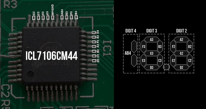
using the datasheet and some tracing with a multimeter I determined that there are 2 full digits used and a half a digit which is the 1, and of course the dot, because I don't care about the dot.
and the conclusion:
Pin BP/GND - its like the common ground for the LCD
Pin AB4 - Drives the "1" first digit
Pins A3-G3 - Drives the second letter
Pins A2-G2 - Drives the third letter (the first after the decimal)
Pins A1-G1 - Not in use (but if you want higher resolution for the pH metering you get it here) I won't be using it
its 15 pins for all segments and one ground
I soldered to each pin a wire (soldering to the LCD pads would be much easier but I wanted it on for debugging)
I took 16 Diodes (1N4001 - this is what I had) and "rectified" the currents, resulting in signals that are about 2.5-2.6 VDC peak
second part is two shift registers (CD2041BE) linked together, every shift register has 8 inputs, so its 16 total.
each input lead connected to ground with a 100K pullup resistor (I think 10K will be enough) and each signal connected to different input pin
Inputs 1-7 -> A3-G3
Input 8 -> AB4
Second chip:
Inputs 1-7 -> A2-G2
made some calculations and matched binary codes to the digits that are showing.
I have used this : http://www.arduino.cc/en/Tutorial/ShiftIn A-LOT, thank you Carlyn Maw
Threw some codes together and got it working :
// Stuffs by AlexShu

int latchPin = 3;
int dataPin = 4;
int clockPin = 2;
int pH_1=0;
float pH_2=0;
float pH=0;

byte switchVar1 = 0;
byte switchVar2 = 0;

void setup() {
  Serial.begin(9600);

  pinMode(latchPin, OUTPUT);
  pinMode(clockPin, OUTPUT);
  pinMode(dataPin, INPUT);

}

void loop() {

  digitalWrite(latchPin,1);
  delayMicroseconds(20);
  digitalWrite(latchPin,0);

  switchVar1 = shiftIn(dataPin, clockPin);
  switchVar2 = shiftIn(dataPin, clockPin);

 // Serial.println(switchVar1, BIN);
//Serial.println(switchVar2, BIN);

// Translating the first two digits
  switch (switchVar1) {
  case B00000110:
    pH_1=1;
    break;
  case B01011011:
    pH_1=2;
    break;
  case B01001111:
    pH_1=3;
    break;
  case B01100110:
    pH_1=4;
    break;
  case B01101101:
    pH_1=5;
    break;
  case B01111101:
    pH_1=6;
    break;
  case B00000111:
    pH_1=7;
    break;
    case B01111111:
    pH_1=8;
    break;
    case B01101111:
    pH_1=9;
    break;
    case B00111111:
    pH_1=0;
    break;
        case B10111111:
    pH_1=10;
    break;
      case B10000110:
    pH_1=11;
    break;
  case B11011011:
    pH_1=12;
    break;
  case B11001111:
    pH_1=13;
    break;
  case B11100110:
    pH_1=14;
    break;
  case B11101101:
    pH_1=15;
    break;
  case B11111101:
    pH_1=16;
    break;
  case B10000111:
    pH_1=17;
    break;
    case B11111111:
    pH_1=18;
    break;
    case B11101111:
    pH_1=19;
  default:
    pH_1=-1;
  }

// Translating the digit after the decimal
 switch (switchVar2) {
    case B00000110:
    pH_2=0.1;
    break;
  case B01011011:
    pH_2=0.2;
    break;
  case B01001111:
    pH_2=0.3;
    break;
  case B01100110:
    pH_2=0.4;
    break;
  case B01101101:
    pH_2=0.5;
    break;
  case B01111101:
    pH_2=0.6;
    break;
  case B00000111:
    pH_2=0.7;
    break;
    case B01111111:
    pH_2=0.8;
    break;
    case B01101111:
    pH_2=0.9;
    break;
    case B00111111:
    pH_2=0.0;
    break;
  default:
    pH_2=-1;
  }

// Calculating pH
pH = pH_1+pH_2;
// Avoiding garbage
if (pH>0){
Serial.println(pH);
} else {
  pH = 0;
}


byte shiftIn(int myDataPin, int myClockPin) {
  int i;
  int temp = 0;
  int pinState;
  byte myDataIn = 0;

  pinMode(myClockPin, OUTPUT);
  pinMode(myDataPin, INPUT);

  for (i=7; i>=0; i--)
  {
    digitalWrite(myClockPin, 0);
   delayMicroseconds(10);
    temp = digitalRead(myDataPin);
    if (temp) {
      pinState = 1;
      myDataIn = myDataIn | (1 << i);
    }
    else {
      pinState = 0;
    }
    digitalWrite(myClockPin, 1);
  }
  return myDataIn;
}
Next plan:
- listen to you yelling at me knowing nothing about electronics
- get some advice on how to make it better
- tidy it up
- use it in my project
Aftermath notes:
- I don't really know it all those diodes are necessary (but I guess its protecting both sides of the equipment)
- Messiest job I ever did, looks like a parallel flux capacitor

some pictures attached, have more, just tell if you need.
I plan to make full description on my blog soon if anybody interested talk to me.
oh, total cost is 11$ for everything, 8$ for the meter (cheapest one is currently 8.25$)
3$ for shift registers diodes and resistors every other thing is scrap i'm sure everyone has
Thank you ![]()

