Didn't know where else to put this post, Mods feel free to move it to the right catagory. ![]() thanks!
thanks!
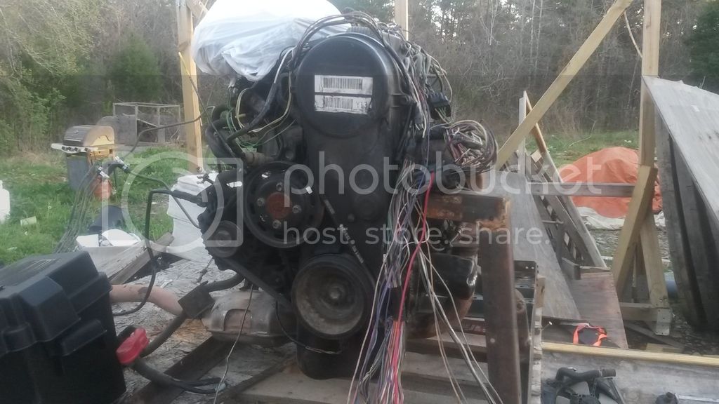
I began a few weeks ago with a 1998 Geo metro....
Now i have the beginnings of a generator. I plan to use Arduino to control the overall function of the generator as well as make the generator smart and IOT/Bluetooth Controlled.
Obviously I plan on using a mega and some other fun bits, but i need a place to store all the information i am creating / researching, so i figure if im going to have the information myself, i may as well share it with the rest of the world. Since this project uses Real and dangerous concepts/ objects/ knowledge, if you aren't aware of what it does, i dont advise you try something like this as well as dont hold me responsible when you drop a battery on your metal fuel tank and blow yourself away... JS
10 seconds of background on me, I am an ASE Master Technitian, I am Certified by 5 Major Dealers to work on their brand of goodness as well as Hybrid certified. I have an associates Degree in Automotive Systems Diagnostics, A bachelors in Mechanical engineering, and am working towards a Bachelors in Electrical engineering, Pretty much if it has electricity in it or serves some human purpose, i can mod/tinker/destroy/fix it. Given this, my care of grammar is very low, use of English is also not a concern of mine. Please do not troll this post, If you are not interested I understand and thank you for looking. I have spent the last two years of my life building Commercial grade Solar Power plants, I also live domestically off the grid ( I am my own water, sewage and electric company)
now for a cool movie....

i would embed it but yeah the forum just isnt cool like that ![]()
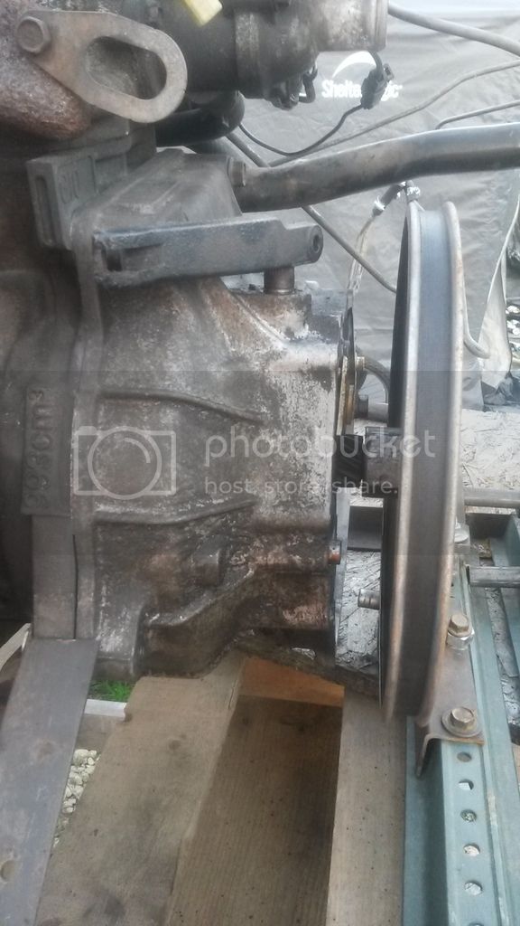
that movie shows what i have so far. I have removed the engine from the car, disassembled the manual transmission, split the case of the trans mission, cut the rest of the input shaft off of the primary gears, reassembled the clutch onto the engine, used the front half of the transmission often referred to as the bell housing, the input bearing, a pulley hub and the biggest pulley i could buy from Tractor supply. i welded the pulley to the hub and used a shop press to force the input shaft from the original transmission into the pulley hub, secured this witht the two grub screws that come on the collar. then using an old broken trundle bed (like this one :: https://images-na.ssl-images-amazon.com/images/I/41K0FE7KtlL._AC_US200_.jpg ) i cut free all of the angle iron and welded a frame. to this frame i cut apart a construction speed limit sign post from one of my job sites into pieces which originally were to serve as a slid-able belt tensioner, since sign post are normally full of evenly spaced holes. however the way the engine sits on the frame the big pulley wasnt far enough forward to work correctly so i drilled 2 holes in a piece of spare angle iron and welded a harbor freight 12mm 1/4" drive socket to the angle iron, over the socket i slif the tensioner pulley from a 2000 s10 which fits nice and snug. when the two holes have bolts in them they pick up all the slack in the drive belt.
the drive belt drives a jack shaft fitted with the smallest pulley i could find at Tractor supply, affixed to a 8" section of 3/4" rod that runs through 2 self centering pillow block bearings and into a GM power steering pump ulley for a 1998 Chevrolet K1500, this pulley being approx. 3 to 4 times bigger than a standard Alternator pulley will be the pulley that will eventually drive 8, 150A GM 1 wire alternators. Giving me roughly 1200A @12VDC at full wide open regulation. or roughly 14KwDC theoretical. probably be more like 12KwDC none the less i only use at max 2500wDC including my server tv and current living accomodations, however this is to be the power plant for my new home so bigger is always better.
the pulley system produces a measured 8400 rpm at the alternator drive pulley, while at idle at a little over 900rpm. standard car alternators have a maximum rotational speed of 20KRPM there for i am desiging this system to spool the alternators at 90% of their max. this will allow me to use much smaller pulse width to the rotors of the alternators and generate far larger electrical Fields in the stators. my plan is also to idle the motor down to around 500rpm to conserve on fuel. also since the pulley is much larger than the flywheel on the engine it adds rotating mass to the crank allowing me to use a smaller rpm range and still maintain a running engine...
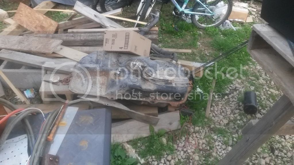
i have reused everything from the car, the fuel tank, sender, engine, fuel lines, all sensors , harness and the stock ecm. was gonna do a speed duino but all i really need to do is monitor the engine the GM guys were paid enough already to figure out how to make it run well. why mess with that?
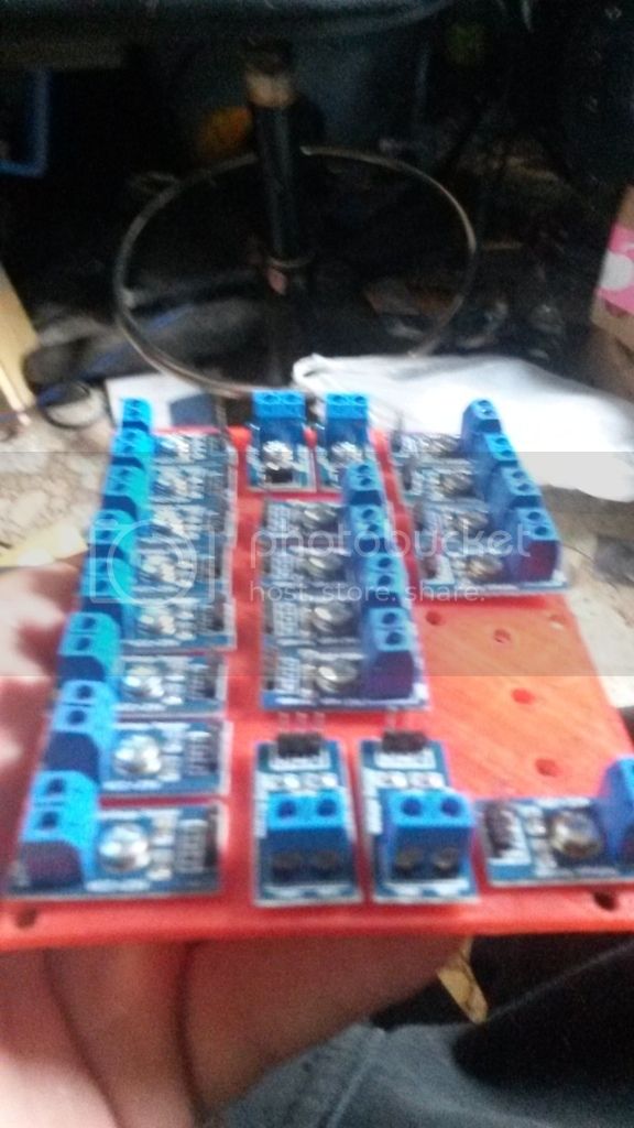
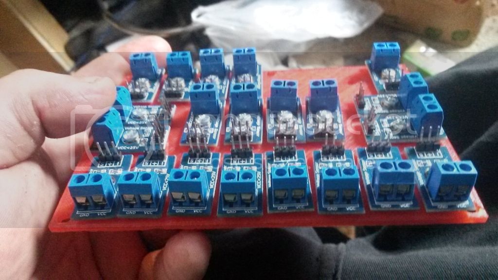
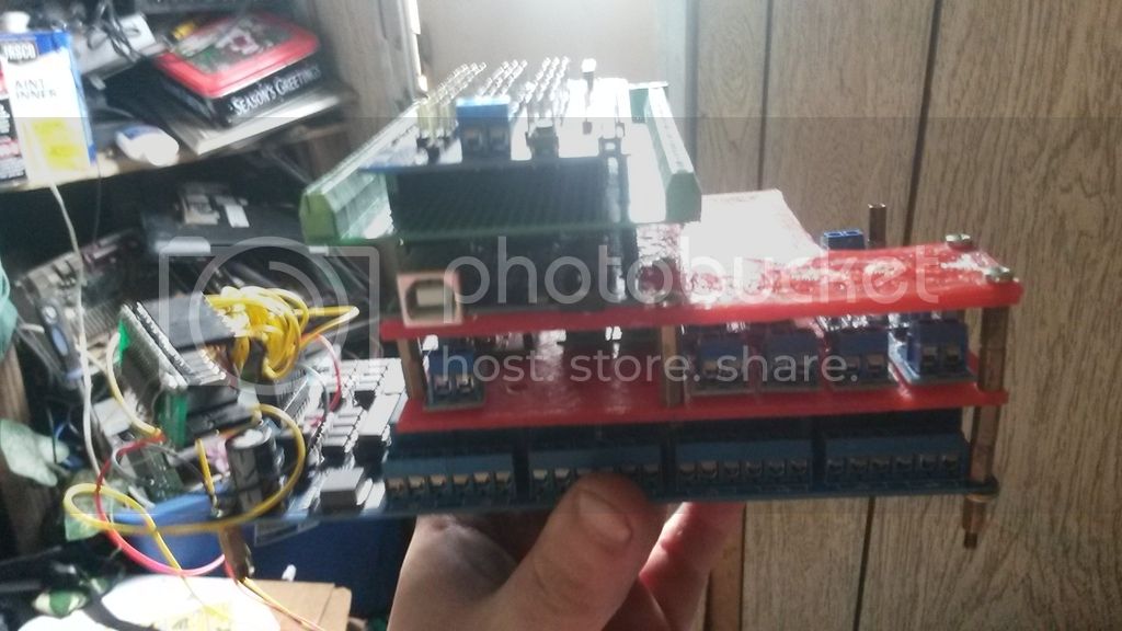
i have 3d printed relay blocks to hold car relays so all of the electronics are native, i also 3d printed the fuse block, and i have deleted most of the emission controls to the engine as they sacrifice engine longevity and power in the name of reduced greenhouse gases, at the rate we are going in this world we are gonna kill each other before we suffocate... js.
Now to the arduino end of things.
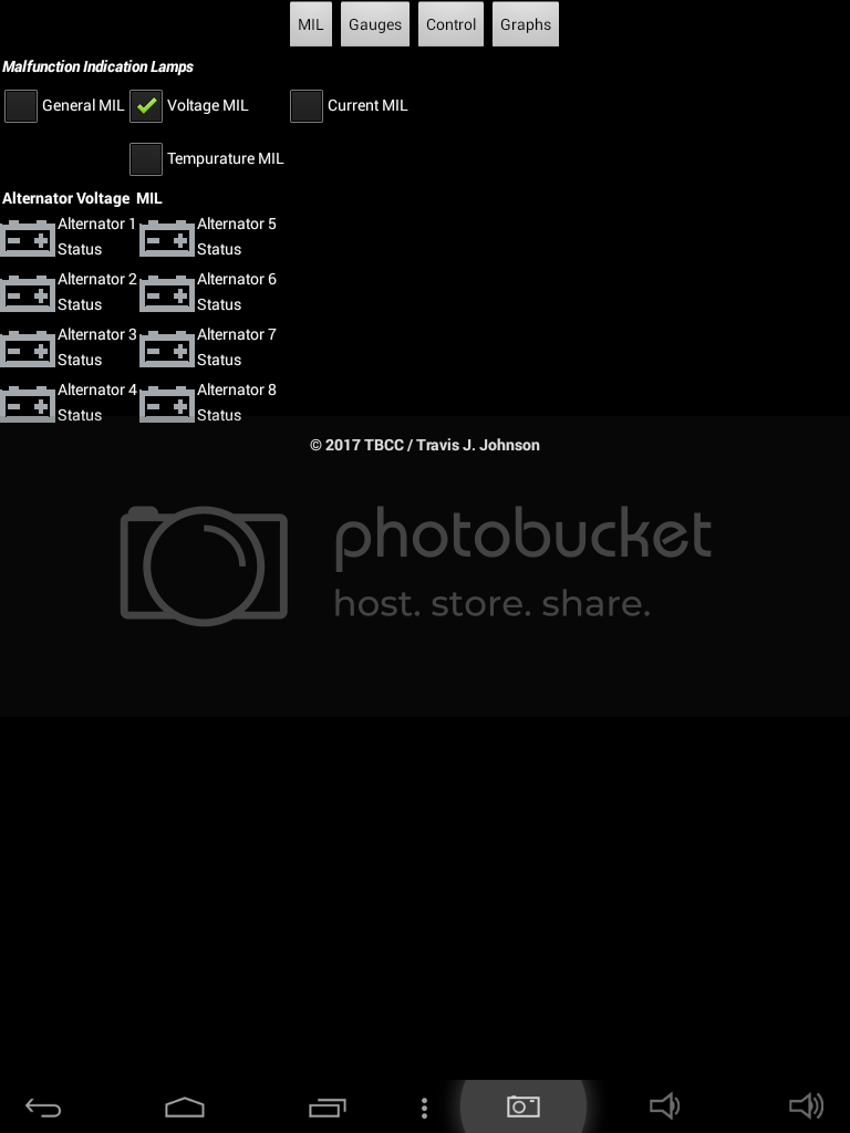
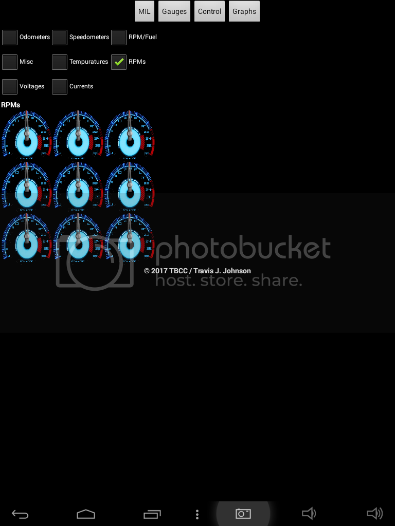
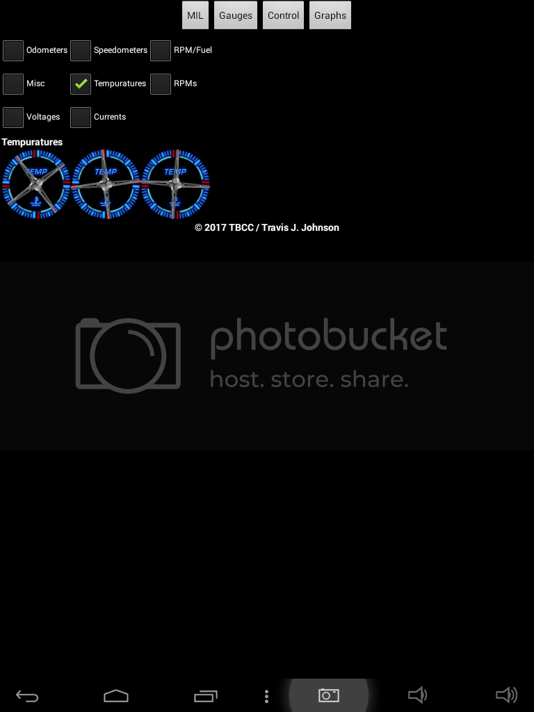
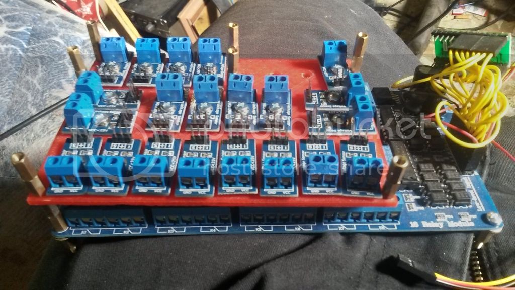
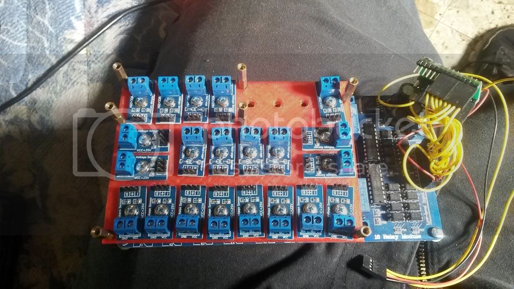
this is my current map of pins i will pull from the stock ecm via splicing the original harness indo the arduino. the arduino will have most of its native adc pins used monitoring the engine vitals. 2 additional i2C ADCs will be attached to monitor the output from the generators. other hardware will include a real time clock and calendar, w5100 ethernet connection, bluetooth, 3.5" touch panel display, and IR tach sensors on each of the alternators, crank and jackshaft. if you have any ideas as to what i could also add i am open to suggestion. Later in the project i will also be adding more control circuitry to control the air conditioning and heat as well as the hot water heater via fluid to fluid heat exchanger.
Map Of ECM Harness:
Digital Inputs
Generatror MIL (9x)
PCM MIL c1-17 PPL/YEL
IG SW Pos. On Custom
IG SW Pos. ACC Custom
IG SW Pos. Start Custom
TP Closed Switch Custom
UpShift MIL c1-18 PPL/RED
EFE On Signal c2-12 WHT/BLK
Dwell FeedBack (Tach Sig) c1-23 BRN (12V?)
Commanded Dwell c1-10 ORN (5v?)
Specialized
ETach IR SENSOR
JTach " "
Atach (8x) " "
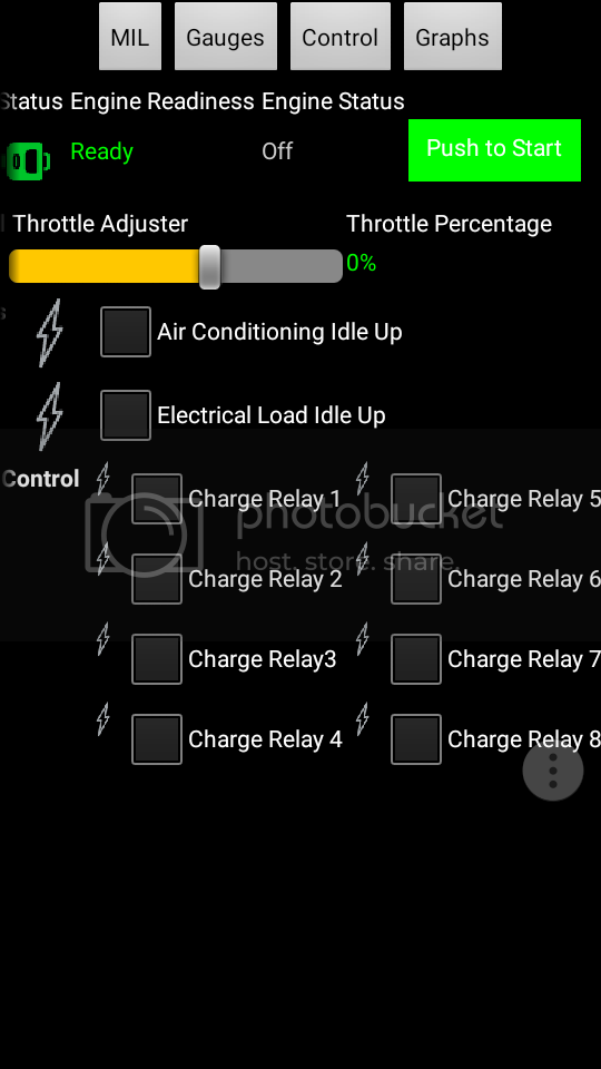
Outputs
Starter Relay Custom
Main Power Relay Custom
Throttle Servo Custom
Electrical Load Idle Up c3-18 BRN/YEL
A/C Load Idle Up c3-19 BLU/RED
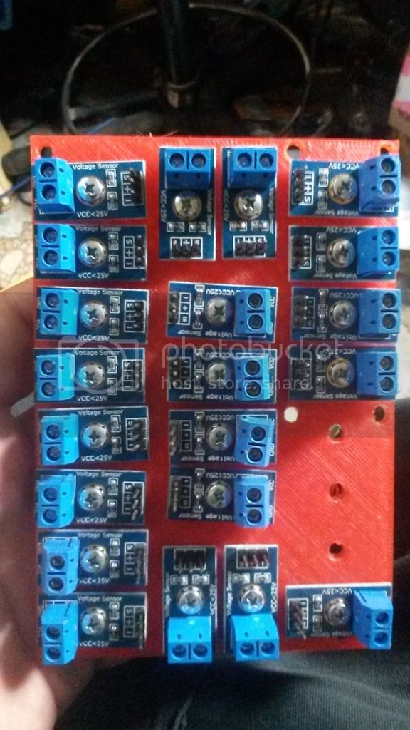
Analog Inputs
Fuel Level c3-10 YEL/RED (?Deleted?)
Gen Battery Level Alt. Pin 2 (Pull Up resistor on ARD.)
Upstream 02 Sensor c2-13 RED
Downstream 02 Sensor c3-08 YEL
MAP Sensor c2-05 LT-GRN/RED
TPS c2-06 LT-GRN/WHT
ECT c2-07 GRY/WHT
IAT c2-14 GRY
Fuel Tank Pressure S. c3-21 LT GRN/YEL
sometime in the next few days i will add some pictures of it in the day light. as well as some harness diagrams... a picture is worth a thousand words.
til then
-T


