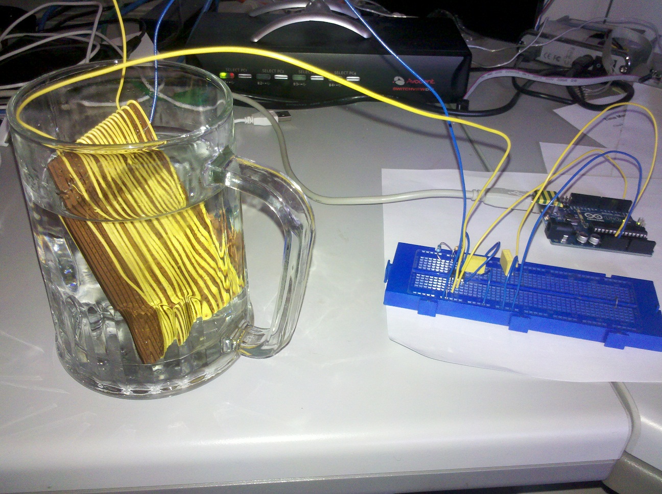
I got sufficiently interested in this that I decided to try it out. I made the sensor by wrapping about 20 turns of insulated wire end-to-end over a piece of stripboard, loosely. I connected the copper strips together to form the ground electrode. This isn't ideal because it allows water to cling between the wire and the stripboard.
My 555 circuit used the sensor as timing capacitor (pins 2/6 to ground), a 100k resistor between pins 2/6 and 7, and a 1M resistor between pin 7 and Vcc. I connected the output pin 3 of the 555 to pin 2 of my Arduino Uno so that I could attach interrupt 0 to it.
Here is the sketch I used:
volatile unsigned long count;

void setup()
{
  pinMode(2, INPUT);
  attachInterrupt(0, isr, RISING);
  Serial.begin(9600);
}

void isr()
{
  ++count;
}

void loop()
{
  noInterrupts();
  count = 0;
  interrupts();
  delay(1000);
  noInterrupts();
  unsigned long freq = count;
  interrupts();
  Serial.print(freq);
  Serial.write(' ');
  float interval = 1000.0/(float)freq;
  Serial.print(interval, 4);
  Serial.write(' ');
  float level = (interval - 0.1200)/(0.9025 - 0.1200);
  Serial.println(level);
}
The first value sent to the serial port is the frequency in Hz, the second is the interval in ms, and the third is the water level. The figures 0.1200 and 0.9025 in the calculation are the intervals I recorded with the sensor out of the water (but still a bit wet) and fully immersed, respectively.
It works! The level displayed goes from 0.0 when the sensor is out of the water to 1.0 when fully immersed, linearly as far as I can tell. The only snag is that with the sensor out of the water, the reading can be a little higher than 0.0 or slightly negative, depending on how much water is clinging between the wires and the board at the bottom of the sensor. When building your sensor, I suggest making sure that the wires or insulated rod are separated from other things (particularly the ground electrode), to prevent water clinging to them. Using water-repellent insulation (PTFE?) might also help.