My goal is to read voltage from either a 2S or 3S lipo-battery which means that to read it with my arduino I need to reduce the voltage. I had some 100K and 10K resistors at home so I built a voltage divider using these. I measured the resistors to be R1=98700 and R2=9790. As can be seen in the code I use a variable called voltage_divider that has these values which I use when reading the voltage. The voltage is read using the Vin pin, there I connect R1 & R2 then connect to ground. I read the voltage over R2 into the A0-pin.
The problem is that I get a value that's close to the correct value but too far away to be acceptable. For example, a voltage of 4.55V reads 4.35V and 11.68V reads 11.45V.
Can anyone spot an obvious error?
#include <LiquidCrystal.h>

//LCD display pinout - YM2004A & OV1604A
//VSS   LCD pin 1     -  Connect to ground
//VDD   LCD pin 2     -  Connect to +5V
//V0    LCD pin 3     -  Connect to potentiometer
//RS    LCD pin 4     -  Arduino pin D07
//RW    LCD pin 5     -  Connect to ground
//EN    LCD pin 6     -  Arduino pin D08
//DB4   LCD pin 11    -  Arduino pin D09
//DB5   LCD pin 12    -  Arduino pin D10
//DB6   LCD pin 13    -  Arduino pin D11
//DB7   LCD pin 14    -  Arduino pin D12
//ELA   LCD pin 15    -  Arduino pin D13
//ELK   LCD pin 16    -  Connect to ground
//LiquidCrystal lcd(7, NULL, 8, 9, 10, 11, 12);
LiquidCrystal lcd(7, 8, 9, 10, 11, 12);

int screen_backlight = 13;                 //pin D13 will control the backlight
float voltage_battery = 0;                 //pin A0
float voltage_divider = (98700+9790)/9790;    //((R1+R2)/R2)*voltage on A0-pin

void setup() {
  pinMode(screen_backlight, OUTPUT);       //LCD Setup
  digitalWrite(screen_backlight, HIGH);    // turn backlight on. Replace 'HIGH' with 'LOW' to turn it off.
  lcd.begin(20,4);                         // columns, rows.  use 16,2 for a 16x2 LCD, etc.
  lcd.clear();                             // start with a blank screen
  lcd.setCursor(0,0);                      //LCD text row 1
  lcd.print("Ui      V");
}

void read_voltage() {
  //Voltage input, U must be lower then 5V, HW-diveded then SW-multiplied
  voltage_battery = analogRead(A0)*voltage_divider*5/1023;
}

void screen_print() {
//Printing battery voltage level on LCD-screen
  lcd.setCursor(3,0);
  if(voltage_battery<10) {
    lcd.print(" ");
  }
  lcd.print(voltage_battery);
}

void loop() {
  read_voltage();
  screen_print();
}
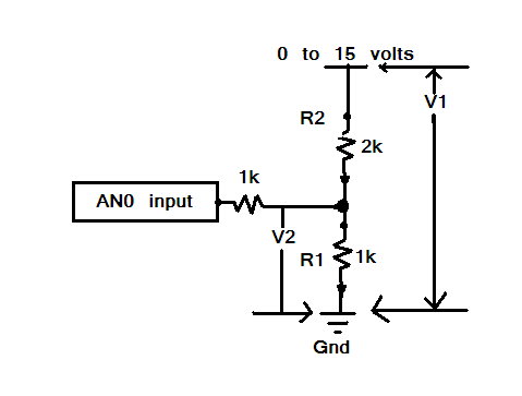
I would change the resistor values to as in my drawing
Then a little math and see if it don't work better
ADC reading  1000 +2000 = 3000 /1000 = 3

check the chips ADC AREF pin say it's 4.89 volt
you can compensate for that in code

so your math is 1000 +2000 = 3000 /1000 = 3 * 5 =(V1) 15

So a ADC reading of (V2) 5 volts = 15 volts
MAS3:
Your voltage divider adds up to about a factor 11, not as a factor 10.
I guess that's what you are tripping over.
That's obviously not the issue if you look at the code.
float voltage_divider = (98700+9790)/9790; //((R1+R2)/R2)*voltage on A0-pin
One issue is that the calculation is in integer arithmetic, and secondly that error of about 2% is perfectly within spec anyway.
That code sets voltage_divider to 11.000.
float voltage_divider = (98700.0+9790.0)/9790.0; //((R1+R2)/R2)*voltage on A0-pin
Will do the right thing. Voltage regulators (such as the 5V regulator on the Arduino that you are using as
the voltage reference for ADC measurements) will normally have a +/- 2% or 5% rating - until you measure
the actual 5V rail voltage and substitute it for "5" in the calculations you can't do any better.
Ok, so to improve the accuracy I could reduce the resistor values or at least the dividing factor so that I get something around 3 or 4 instead of 11. This should make the accuracy a little better right? I want to be able to connect up to 4S-battery (16.8V) safely.
The 5V supply from the arduino seems to be a pretty solid 5V when I connect an external battery. I get 5.00V on my multimeter and when I power it using USB I get 5.06V. Or do you mean another 5V-rail then the 5V-output pin?
Your measuring range with the original divider is too high.
I will gladly admit i didn't look at the code to see that you are using a formula that takes the number 11 as the divider.
But this way your maximum reading of 1023 would represent about 55 volts.
Therefore it would be better to try to get as close as possible to the actual range you are in.
So if you have 12 volts, and with the available resistors, i would use R1 as is, and instead of R2, 2 10K resistors in parallel forming a resistor of about 5K.
This would put you in a range of 15 volts, about 3 times better than where you are at now.
You then are measuring more accurate, because you have more bits to divide per voltage, so calculating with the measured result will also be more accurate.
Don't confuse "resolution" (bits per volt) with "accuracy" (precision of measurement)
Increasing resolution will help with determination of measurement but it does not necessarily increase "accuracy", which depends on your Vref, ADC precision and input resistor tolerances. You cannot get "accurate" results if you use 10% tolerance, high temp coefficient resistors. And don't say you've already measured their values with your digital test meter. What level of precision does that offer ?
On the other hand, measurement is a "relative" thing. If you use your personal test meter as your "in-house standard" then all well and good since all subsequent measurements are referenced to it - not to precise national standards. For example, I'm quite happy to use my cheap and nasty test meters as my reference standards but cannot ever consider them "accurate" - just good enough for my needs.
Now I've reduced the voltage divider and use R1=2990 and R2=984 and yes I do use my calibrated Fluke to measure everyting (as well as a cheapo but quite accurate meter). This will not need to hold any kind of indistry calibration standard but I need it to be as close to my meters as possible.
Now I get the following results:
Power over USB: 4.32V (arduino), 4.47 (on my meters), 3.35% diff
Power over 3S: 11.52V (arduino), 11.66V (on my meters), 1.2% diff
Of course I'd like it to be even better so I guess I should now start investigating this VREF that I guess is how the arduino close the arduino 5V supply is to 5V. Is that correct? Is there a prefered method of doing this?
That's an overly simplistic, black-and-white view of a highly complex world.
For example, I can point to multiple cases where the "wrong" approach is correct and the author's "Very nice. very elegant. And, more importantly, very useful." approach is "wrong".
What the author forgot to mention is that what's right or wrong is highly application specific so it is wrong to insist one approach is "wrong" while the others "right".
The spec sheet gives a nominal value of 1.1 volts, but states that it can vary from 1.0 to 1.2 volts. That means that any measurement of Vcc could be off by as much as 10%. Such a measurement could be less accurate than our power supply for the Arduino!
How much more 'accurate' are you expecting things?
A couple of percent looks pretty good really. There are a number of things that are going to affect the readings you get between your multimeter and the analog ports via voltage divider.
Your Arduino analog ports have 8 bit resolution. Your multimeter most likely has better than 8 bit resolution.
Your multimeter has limits. It will have accuracy fingures given in both percentage and digits (if digital).
Your reference voltage may not be exactly 5v, and will vary slightly with the load on that supply line.
Your resistors have a tolerance. Are you using 5% or 1% resistors. They will also vary as they will have a temperature coefficient.
You are measuring the resistances too, which again will be within the measuring tolerances of your meter AND at a specific temperature that can change.
Combine all of these and what you are seeing is actually pretty good as far as I can see.
You're measuring with two different instruments, in different ways, with various things that have errors and tolerances.