Using a three-way toggle switch for power and digital input

Hi,

I want to use a three way toggle switch to let the user select two modes of operation and also switch off the Arduino completely (to save power). I'm using an Uno R3, in case that is relevant.

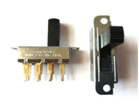
The switch is type B from here: http://www.maplin.co.uk/sub-miniature-toggle-switches-2341

When the switch is in the middle "off" position none of the three pins are connected. When in either "on" position (left or right) the middle and left or right pins are connected.

I have completed a test circuit where the state of the switch is read (left position on one digital pin, right on another, both using pull up registers), and two different LEDs are illuminated, one for each switch position (the LEDs were connected to other pins and controlled by the program). With the switch in the middle position both LEDs are off.

That was the easy part. Now I'd like to connect a battery (using a snap on 9V battery connecting to the DC barrel jack), with the switch between the battery and the DC barrel. When the switch is in either on position, I want the Arduino to get power but also read which way the switch is toggled so that the program can operate in one of two different modes. I understand the digital in must not be connected the +9V on the battery, but could I interrupt the ground connection from the Arduino to the battery with the switch, joining each pin to ground and the left and right ones to a digital pin for input?

Or is it just not a good idea to mix the power with the logic pins? I feel there is either a fundamental gap in my knowledge here or I'm trying to do something that isn't possible! :~

I have considered using the switch to control the two modes and a separate switch for power, but I see this as a more elegant user interface.

Any help greatly appreciated.
Simon

For what you want to do, I would suggest a DPTT switch. One side for the power, and the other side for the switch states.

but could I interrupt the ground connection from the Arduino to the battery with the switch, joining each pin to ground and the left and right ones to a digital pin for input?

I can't quite visualise that, maybe you should post a diagram. Won't you still be putting 9v to the digital pins?- although as a I say, I can't picture it.

I think what you want is a double pole on-off-on switch. For example: http://www.ebay.com/itm/2-x-3-Way-Design-AC-125V-6A-Double-Pole-DPDT-On-OFF-On-3P-Toggle-Switch-Blue-/121079700806?pt=Guitar_Accessories&hash=item1c30e99d46

The switch has 6 contacts, 3 on one side (A-B-C) and 3 on the other (D-E-F). When it is in the first ON position, A is connected to B and D is connected to E. In the middle OFF position, none of the wires are connected, and in the second ON position C is connected to B, and F is connected to E. As the ebay listing shows, these types of switches are used with electronic guitars, and can have more poles, such as a triple on-off-on switch. Just to be sure, use a circuit tester to make sure there is no connection between the A/B/C side and the D/E/F side, as you don't want to feed 9v into the Arduino.

So you connect the + of the 9v battery to the B terminal. Connect the A and C terminals together, and connect both wires to the + terminal on your 2.1mm power connector. You connect the - terminal of the 9v battery directly to the 2.1mm power connector. Thus when you put the switch into either ON position, power flows to the Arduino.

Then you connect the Arduino ground to the E terminal, and two digital pin inputs (lets say pin 2 and pin 3) to the D and F terminals. If the switch is in the first ON position, pin 2 would indicate a connection (LOW or HIGH depending on if you are using internal pullups or resistors to ground), and pin 3 would be the opposite. If the switch is in the second ON position, pin 2 would be off, and pin 3 would indicate connection. You then control the LEDS as appropriate. Note, you would have to have the switch on long enough while the Arduino determines that it isn't being reprogrammed.

Another way to do it that I know in theory, but I haven't done, is use pins 2 and 3 as the two on switches, and connect them to interrupts when the state changes. Then put the Arduino to sleep. When the contact is made, the Arduino is woken up. While it uses some power, it should use a lot less than normal operation. Nick Gammon covers this is in his power saving tutorial: Gammon Forum : Electronics : Microprocessors : Power saving techniques for microprocessors.

A third way to do it with a single pole switch, would be have the 9v power feed into an opto-coupler or relay that would be connected to the Arduino pins. I.e. using A/B/C, if A & B are connected, you have a wire that connects to the power, but you also have a shunt to turn on the opto-coupler, and the Arduino would use the other end for digital input. However, I tend to think the double pole on-off-on switch is simpler. With an opto-coupler, you probably want to put in a resistor so that you don't burn out the LED inside of the opto-coupler by feeding it 9v.

A fourth way would probably be a voltage divider and resistor to reduce the 9v to be acceptable to the Arduino. However, I would want to have a better grounding in electrical theory before even attempting it.

Thanks for the replies.

HazardsMind - I'm not familiar with these, but a quick Google search suggests the switch has separate connections for power and to read the switch position? So it could have 6 pins - three for the power (one for off the other two for on) and three for reading the state. When you flip the switch it completes two separate circuits?

JimboZA - What I mean is to snip the negative wire between the battery and the DC jack and wire in the switch. So after the forward voltage of the Arduino is taken into account (and using any resistors needed) would it not be less than 9V? This is probably my misunderstanding here (I'm a newbie) but I'm trying apply what I know and the fact I'm stuck means I'm not grasping something. I assume the negative on the battery completely separate to the common ground on the board?

MichaelMeissner replied as I was typing this, but I'll leave my above responses in place, but it looks like I was on the wrong path so no need to respond.

MichaelMeissner - I assume this is the type of switch JimpboZA suggested and confirmed my assumption on how it works. Many thanks. I need a switch that locks into place so the Arduino remains on continually until the switch is flipped off. I've read about the Arduino sleep function, thanks for the link I'll look into it further as another option.

Thanks again.

When you flip the switch it completes two separate circuits?

yep

struddie:
MichaelMeissner - I assume this is the type of switch JimpboZA suggested and confirmed my assumption on how it works. Many thanks. I need a switch that locks into place so the Arduino remains on continually until the switch is flipped off. I've read about the Arduino sleep function, thanks for the link I'll look into it further as another option.

Yes. You presumably want both switches to be locking switches and not momentary switches.

I assume this is the type of switch JimpboZA suggested

Ummm, much as I'd like to take the credit, I didn't suggest a thing!

Appologies, it should have been DP3T, not DPTT (Double Pole, Triple Throw)