I have been trying for a while now to get a very simple Blink LED program to work on an Arduino setup on a breadboard. I have used the tutorial on the Arduino site as well as a bunch of other searching on the web and I cannot seem to figure out what my problem is. I have a power LED on my setup and I have checked the voltages with a multi-meter so I know/think that power is getting to the chip, but the Blink LED program does not appear to be executing. I can take this same chip and put it back into my Uno and it runs just fine. The power supply is a 9 volt battery it can also power the Uno just fine.
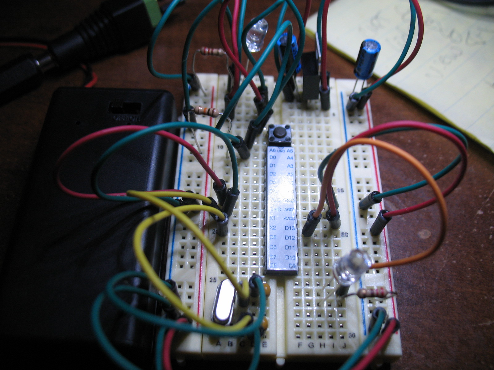
I attached a couple of pictures of the bird's nest I have created. I think the setup is pretty standard but I must be missing something, right?
Anyway, if any of you more experienced folks have the desire to stare at them for a bit maybe you will see something that my newbie eyes do not.
I can't see anything obviously wrong, but it is not all that easy to see from the pictures. Have you made sure the pin 13 led is wired the correct way with anode towards the resistor/output pin? Maybe a quick measurement of the pin one reset voltage with a meter to be sure it's at +5vdc. If all that is correct I would play around with the crystal and related components and wiring.
I uploaded the sketch by putting the chip in my Uno and uploading it normally. Then removed the chip and placed it on the breadboard.
The LED connected to pin 13 is connected correctly. (Triple checked) Also tried it with it backwards
The LED connected to pin 13 does NOT blink when the chip is reset or when power is applied. Seems that is another symptom of the same problem.
I have tried it without the crystal and loading capacitors and also same result. I have tried moving them around in different configurations as well. What is pictured was just the latest iteration.
Have checked pin 1 and it is getting 5V and gets nothing when the reset button is held down.
Thanks for the suggestions and your time to this point.
Double check the values of those caps used with the crystal, read the nomenclature and post it here exactly as printed on the caps. Wrong values (too high) can cause oscillation not to happen.
Pabby:
I have tried it without the crystal and loading capacitors and also same result. I have tried moving them around in different configurations as well. What is pictured was just the latest iteration.
Was one of the permutations that you tried plugging the crystal directly into the breadboard X1 and X2 connections, no long wires, and no loading caps?
Lefty, you are the man. I think Jack is the man as well because he asked if I was sure of the capacitor values and I dismissed it as "Well, duh I know what value they are". Turns out I was wrong.
Looked at both capacitors and one of them was 22pF and the other was 0.1uF. So I replaced the wrong one and now it works.
True newb mistake I suppose.
Thanks very much for your time and help. Ill be much more careful in not taking things like that for granted in the future.
Great! Glad to hear it's working. Those 0.1uF caps will slow the clock right down, won't they! I am continually putting those small ceramic caps under the magnifier; having had too many birthdays it's just about impossible to read those tiny letters. How do they print them, anyway, laser?