Hello there,
i havent found anything similar and as basic as my problem, so I am opening a new post. i am a relative noob, so I beg your pardon ![]()
Hello there,
i havent found anything similar and as basic as my problem, so I am opening a new post. i am a relative noob, so I beg your pardon ![]()
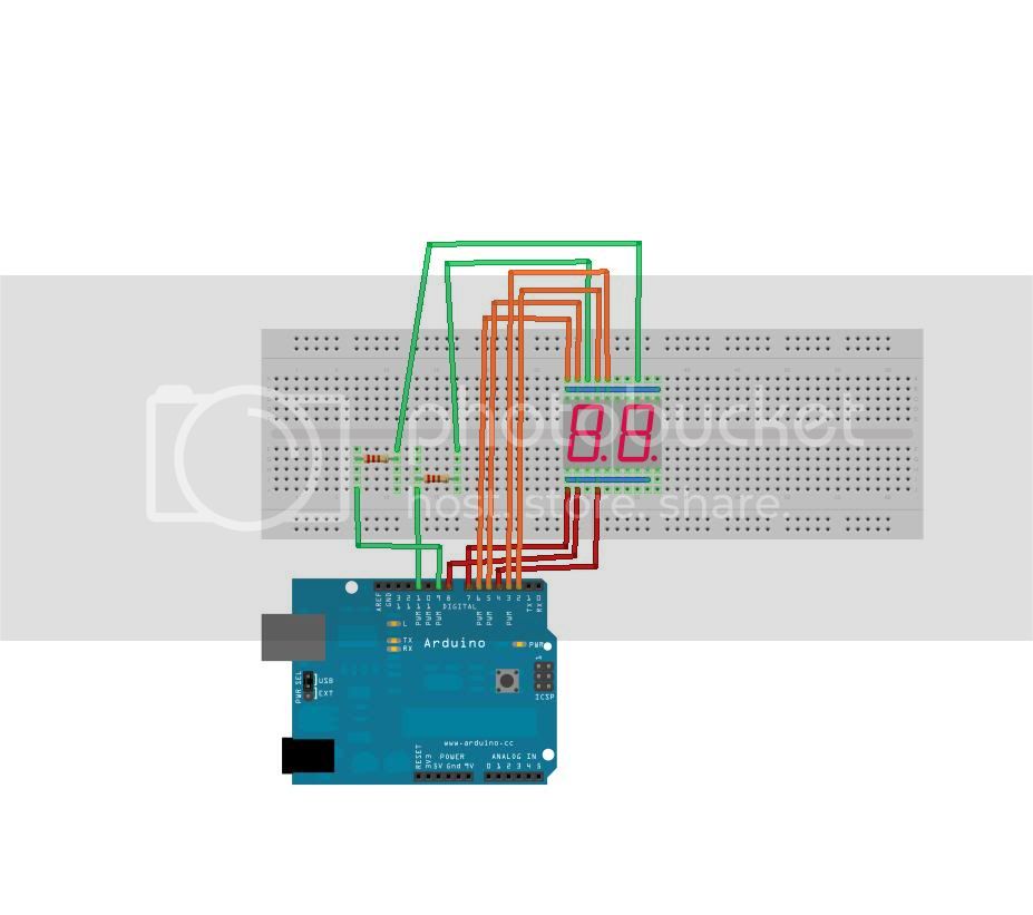
i want to run a 2 digit 7 segment display, as done so in this instructable:
in the instructable project the author is using an SMD 2digit 7segment display with a common cathode. apparently its 2 digits in one component
i want to use two single KINGBRIGHT SC52-11EWA
datasheet: http://datasheet.octopart.com/SC52-11EWA-Kingbright-datasheet-513290.pdf
since i did not want to solder the multiplexing circuit --like in the instructable-- i made the connections between the single displays on the breadboard.
now,
please, maybe somebody has a hint
thank you

- i am getting glyphs that do not match numbers
This will be caused by your software putting out the wrong bit pattern to the LEDs
- the two displays show the same number
This will happen if your software is not multiplexing the LEDs, that is putting the bit pattern for one display on the outputs and then turning that display on.
Delaying some time then turning that display off and putting the the bit pattern for the other display on the outputs and then turning the other display on. This action is called multiplexing and needs to happen continuously.
I notice that you only have one resistor limiting the current for each display. This is very bad and means that the segments will vary in brightness depending on how many segments are on. There should be a resistor in line with each of the segments and no resistor in the common line.
how do i post code that is longer than 9500k?
9.5 Meg of code !! :o
That code (in the link not what you have just posted) is rubbish. It doesn't do any multiplexing at all, it won't even begin to work.
In your code
Change delay(0.5);
to delay(100);
This might let you see something but it is a totally rubbish technique.
Delaying some time then turning that display off and putting the the bit pattern for the other display on the outputs and then turning the other display on. This action is called multiplexing and needs to happen continuously.
-->is this even done in this loop?
do i have to switch the first display off, while the second display is on?
do i not do this by setting the gndpins 1 and 2 on and off?
please excuse my miserable knownledge of all this.
great, now. with the delay on 100 i can see that i can modify each segment:)
void loop() {

//                            --1--
//                         3 |     | 2
//                           |--5--|
//                         6 |     | 4
//                            --7--

   digitalWrite(pin1, B1);
   digitalWrite(pin2, B1);
   digitalWrite(pin3, B1);
   digitalWrite(pin4, B1);
   digitalWrite(pin5, B0);
   digitalWrite(pin6, B1);
   digitalWrite(pin7, B1);
   digitalWrite(gnd1, B0);
   digitalWrite(gnd2, B1);
   delay(10);                                        //          Writes 00 to the display.
   digitalWrite(pin1, B1);
   digitalWrite(pin2, B1);
   digitalWrite(pin3, B1);
   digitalWrite(pin4, B1);
   digitalWrite(pin5, B0);
   digitalWrite(pin6, B1);
   digitalWrite(pin7, B1);
   digitalWrite(gnd1, B1);
   digitalWrite(gnd2, B0);
   delay(10);

}
i changed the pin numbers accordingly, everything works fine.
the gnd1 and gnd2 values of both segments just have to differ? or is there another reason to change them.
This might let you see something but it is a totally rubbish technique.
--> whats a better way to do this?
ok, now that I / we have gotten this to work, i want to add another digit. i will clean up the breadboard, pins allocations, code and the fritzing diagram.
wiring:

code:
// 3x7SegmentDisplaysMultiplexedOnBreadboard
//
//
//
//                            --6--
//                         5 |     | 7
//                           |--4--|
//                         1 |     | 3
//                            --2--


int pin1 = 2;
int pin2 = 3;
int pin3 = 4;
int pin4 = 5;
int pin5 = 6;
int pin6 = 7;
int pin7 = 8;
int gnd1 = 11;                                   //                          gnd1 is display 1's gnd
int gnd2 = 10;                                   //                          gnd2 is display 2's gnd
int gnd3 = 9;                                    //                          gnd2 is display 3's gnd

int timer = 500;                                 //   A timer, to run the for loop 500 times, which turns out as 1 second.
int value;                                       //   The value, part of the FADING display

void setup(){
  pinMode(pin1, OUTPUT);
  pinMode(pin2, OUTPUT);
  pinMode(pin3, OUTPUT);
  pinMode(pin4, OUTPUT);                         //The following sets up all of the pins for use.
  pinMode(pin5, OUTPUT);
  pinMode(pin6, OUTPUT);
  pinMode(pin7, OUTPUT);
  pinMode(gnd1, OUTPUT);
  pinMode(gnd2, OUTPUT);
  pinMode(gnd3, OUTPUT);

}

void loop() {
   // Writes 000 to the display.
   digitalWrite(pin1, B1);
   digitalWrite(pin2, B1);
   digitalWrite(pin3, B1);
   digitalWrite(pin4, B0);
   digitalWrite(pin5, B1);
   digitalWrite(pin6, B1);
   digitalWrite(pin7, B1);
   digitalWrite(gnd1, B0); // apparently 0 means on in this case
   digitalWrite(gnd2, B1); // and 1 means off
   digitalWrite(gnd3, B1);
   delay(5);
   digitalWrite(pin1, B1);
   digitalWrite(pin2, B1);
   digitalWrite(pin3, B1);
   digitalWrite(pin4, B0);
   digitalWrite(pin5, B1);
   digitalWrite(pin6, B1);
   digitalWrite(pin7, B1);
   digitalWrite(gnd1, B1);
   digitalWrite(gnd2, B0);
   digitalWrite(gnd3, B1);
   delay(5);
   digitalWrite(pin1, B1);
   digitalWrite(pin2, B1);
   digitalWrite(pin3, B1);
   digitalWrite(pin4, B0);
   digitalWrite(pin5, B1);
   digitalWrite(pin6, B1);
   digitalWrite(pin7, B1);
   digitalWrite(gnd1, B1);
   digitalWrite(gnd2, B1);
   digitalWrite(gnd3, B0);
   delay(5);
}
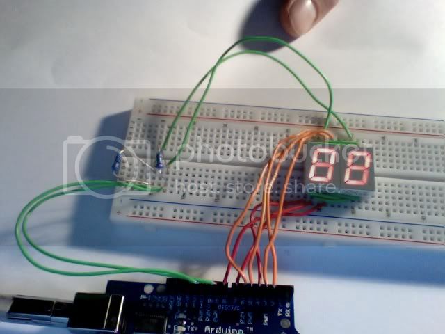
its working!!!...
to the human eye it looks perfectly fine,
but as you can see in the picture --and told me already -- the segments vary in intensity. i assume that the resistors are at the wrong place.
... and off to the next problem. this is so much fun.
if i m gonna make this happen properly, i could make a tutorial for newbies out of this thread.
I notice that you only have one resistor limiting the current for each display. This is very bad and means that the segments will vary in brightness depending on how many segments are on. There should be a resistor in line with each of the segments and no resistor in the common line.
how am i going to fit all the resistors on the board?
what is the correct way of doing this?
can i just switch the resistors? meaning: putting resisors on each pin,
and leave them out on the ground pins?
thx
can i just switch the resistors? meaning: putting resisors on each pin,
and leave them out on the ground pins?
Yes you can. Each of the 7 segment pins should have a resistor of it's own. That's one per pin not one per segment as you connect 2 or 3 segments to one pin.
But then you run into another problem. The cathode pins will not be able to sink the current from all the LED segments when they are all on. The pin (all pins on this processor) has a current limit of 40mA. Any more and you damage it.
You can limit the current through the LED to one eighth of the maximum that is 5mA or 700R.
The real solution is to drive the pin through a transistor (then writing high will mean on and low will mean off).
i swapped the transistor allocation.
now theres a resistor on every pin line
instead of on ground line.
is this ok to do?
it looks good, but when i make a video of it, the segments flicker.
is there supposed to be a resistor on every pin?
puzzled

but when i make a video of it, the segments flicker.
Does it flicker when you look at it?
A video of a multiplexing device will always flicker because of the strobe effect between the frame rate of the video and the refresh rate of your multiplexed display.
ok. so thats putting resistors on every segment-pin of the digits,
and putting a transistor(wich one?) on the cathode?
But then you run into another problem. The cathode pins will not be able to sink the current from all the LED segments when they are all on. The pin (all pins on this processor) has a current limit of 40mA. Any more and you damage it.
You can limit the current through the LED to one eighth of the maximum that is 5mA or 700R.
how do do this?
The real solution is to drive the pin through a transistor (then writing high will mean on and low will mean off).
i hope this still makes sense,
is it better to work with an IC like the MAX7221?
also, later i want the 3digit display to show values from analog inputs.
is this too much for the atmega168?
when i look at it it doesnt flicker, even at a delay(5);
thank you for helping
and putting one on the cathode?
No.
whats a better way to do this?
Segment labeling
//       --a--
//    f |     | b
//      |--g--|
//    e |     | c
//       --d--

// define the pins connected to the segments
#define a 3
#define b 4
#define c 5
#define d 6
#define e 7
#define f 8
#define g 9
// these don't have to be consecutive numbers
// they go into an array so we can reference them
byte segmentPin[] = { a, b, c, d, e, f, g};

byte segmenPattern[] = { 0x3f, 0x06, 0x59, 0x4f,0x66, 0x6d, 0x7d, 0x07, 0x7f, 0x6f};

// then when you want to set the bits to a number
void setSegments(byte num){ // sets the segments according to the number passed to it
   byte mask = 1;
   for(int i=0; i<7; i++){
     if((segmenPattern[num] & mask) == 0) digitalWrite(segmentPin[i],LOW); else digitalWrite(segmentPin[i],HIGH);
 mask = mask <<1;
 }
}
You get the idea?
well.
i am not too sure if multiplexing the displays is still the right method to achieve my goals.
as i mentioned earlier, i want to read a value from an analog in, and display that value on the display. there also hast to be a conversion happening.
so i figured it would be better to drive the displays with a max7221 chip. is that the right thing to do?
Well the chip does the look up and multiplexing for you but costs quite a bit of money. You haver to trade off the time spent programming against the cost of the chip. Personally I have always found that chip just a bit too expensive for what it does but it depends on the application.
hehe,
seems like we are writing posts at the same time, sorry for this.
i d rather not use the max7221 since i m not getting it to work for some reason.
i opened this thread because i thought it would be a good resource for beginners like me to get the first 7segment display working. i want to clean up the thread later, and have it done the right way.
ultimately, my plans for the project are others. i want to read a value from an analog input, convert this value into one that i ll display on the 3 digits.
is multiplexing without the max7221 chip still a good way to do this?
if not -- how should i wire the resistors?
cheers