I don't know if this is the correct forum for this, but none of the other seemed appropriate, so here it is. I'm having difficulty understanding how stacking headers are supposed to work. The issue is that when you fit a shield with stacking headers onto an Arduino it will hit the USB plug and the power socket, and it won't sit flush. The male headers don't have this issue as they have that plastic spacers between the board and the tops of the Arduino headers. Is that really the way it's supposed to be? Sort of at a weird angle, not really plugged in all the way?
I couldn't find any info online on this, and it seems that all the photos of Arduinos on the internet are taken from the analog input side, which doesn't help. Is there a proper way of installing those stacking headers or that's just the way things are?
All the "stacking headers" I've seen on shields have pins that are as long (or longer) than non-stacking headers even including the plastic spacers, so they "bottom out" in the mating connector, and are flat.
Perhaps you have some incorrect headers?
I'm having trouble uploading images. I get some sort of security issue, so I assume I don't have enough posts to do that. In any case, the headers are installed like in the above image, the board on the right. But when I plug it into the Arduino, the shield comes in contact with the USB plug and leaves a gap between the bottom of the shield and the top of the headers on the Arduino board. Male headers have that plastic spacer that fills that gap.
Does that make sense or should I find a way of getting an image to you guys?
See the guide on inserting images in your posts (click !) (the same as posted before).
If you keep getting this error, the problem might be that you took the picture with a phone that adds your location to the picture.
That would mean people can see your location, which is a security issue you might not be aware of.
Convert the picture to the *.png format to get rid of that stuff.
It is one of the allowed file formats for attachments.
Usually, the stacking headers have extended length pins exactly to prevent what you described.
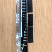
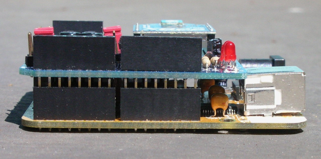
I can't believe it's so hard to post an image... in any case, here it is. You can see the gap at the bottom of the picture between the shield and the Arduino.
The headers aren't soldered yet cause it didn't seem like this is the way it's supposed to work.
I googled "arduino extended headers" and found some results which might be of interest to you.
The first result will lead you to a renowned (because of excellent support) shop and a product that might replace the headers you've got now.
Read the description before you order, so you'll know exactly what (and why) you will get.
Thank you for the link. The pins I have are from Adafruit. And the pins are long enough, if that's what you're referring to. Maybe we don't get the same search results, but the first result took me here. The issue I'm having is with the gap between the shield and the Arduino headers, due to the shield bottoming out on the USB plug. I just want to know if that's normal or if I'm doing something wrong.
Robin2:
I guess that is shorthand for "I can't be bothered"
...R
I apologise if that's the impression I gave. It's shorthand for "oh boy... it was pretty difficult getting one image up, now I need to get another, and it will take a while because sleep and work are important, but I will if it solves the issue, even though I'm not entirely sure how."
So I'll post the image flipped 90 degrees, if it helps. But it will take a while cause job.
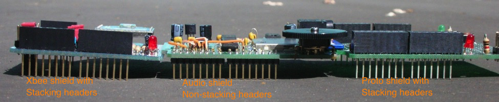
I checked by boards/shields. With the adafruit shields, the stacking connectors "bottom out" right about the same the shield bottom hits the top of the USB connector. Most of my shields have been designed to either not extend over the USB connector, and/or not to have any through-hole components over the USB connector (whose leads might short out against it.)
It looks like your board will fit about the same, once the connectors are soldered - the board will touch the USB connector, but the shield will also be "secure."
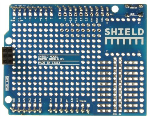
Here's a commercial proto shield with ... nothing on the bottom over where the USB will be, and a photo of some of my mated boards...
I've got this W5100 network shield (which has been running perfectly in some test setup for over a year now), which has its through hole network connector right over the USB connector.
It doesn't touch and the shield fits perfectly to the Duelmilanove (which is very similar to the Uno, but a bit older design).
So it must be fabricated using larger pins.
So i clicked my google search above.
Indeed results have shifted between first and second, and my results have some in my native language which will probably not be there in yours unless we have the same native language.
But i did find a result on the first page, leading to even longer extended leads.
They are 15 mm instead of the 10 mentioned by Adafruit.
The commercial link leads to this shop which seems to be British as it shows its prices in GBP.
So if you have some finished design and are now stuck because of this, try to see if you can get to these 15 mm length headers.
I'd start at the page mentioned above.
The issue isn't that the shield touches the USB plug. Indeed, the shield is designed to do that and has no exposed traces in that area. The issue was that there is a gap left between the shield and the Arduino headers. The stacked headers on the shield make contact, so the shield works. It just looks like bad design to me, so I thought I was doing something wrong.
The issue was that there is a gap left between the shield and the Arduino headers
That would take higher headers on the main board to fix. Or some sort of post-soldering spacers added to the shield. Either would be pretty painful from a sourcing/manufacturing PoV. The "gap" is normal, and the stacked header should seat nearly "all the way" anyway.