I have 2 KMPS 8550 and 2 KMPS 8050 transistors, and I know it is possible to create a H-bridge with these 4, I just don't know how. Would anyone have some hints or schematics? I'm working on a fritzing sketch I'll post later, to see if I'm headed in the right direction.
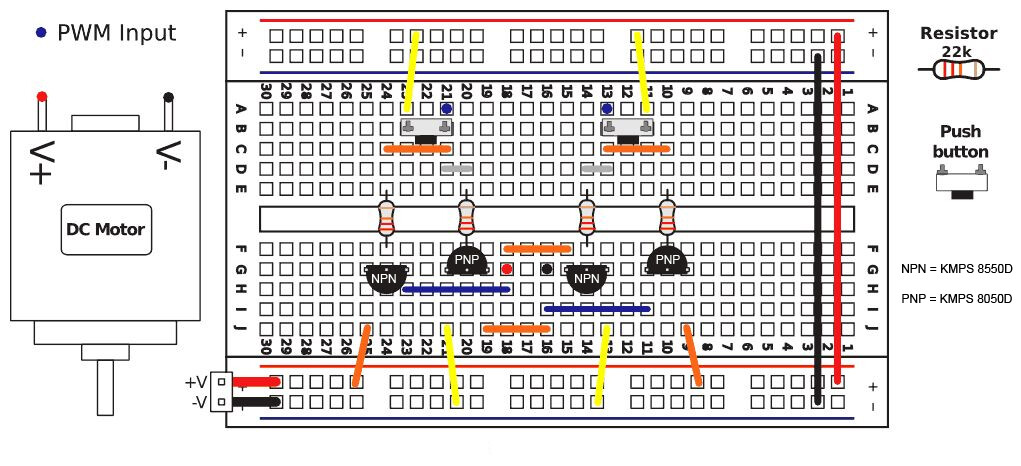
EDIT: I attached what I'm thinking of doing. Is that correct? I also want to replace the button by joining the 4 resistors by group of 2 (like the 2 buttons do), and link both groups to 2 different pins in order to control the motor from the Arduino. Would that be ok?
The .jpg image should be changed so the motor pin names are unique : red black.
The error in the image is the duplicate V+ and V- pin names used for two wrong ideas.
I would use V+ as a VCC power supply and V- as a GND power supply.
Erase the two pin names from the motor and call them RED and BLACK.
Then connect the dots, red dot to RED pin black dot to BLACK pin.
You've got the PNP transistor pin outs wrong and labelled NPN/PNP incorrectly on the RHS.
PNP are the high side switches, NPN low-side. collectors to the motor, emitters to the rails.
You also have a circuit that will burn out if you press both buttons at the same time!
Attached is what I finally came up with. It DID work. I tested it, the motor was spinning accordingly to the pins configuration. But at some point I accidentally plugged the + of the breadboard in to the ground of the arduino and the - of the breadboard in to the 3.3V of the arduino. It took me like 5 secs to realize, so I unplugged everything. And now it's not working anymore. Is it possible that I burnt something out?
EDIT: Ok so now, I replaced the buttons with wires going to pin 12 and 11 of the Arduino. It doesn't work on the Arduino.
With a 3V battery, here is what happens: if I plug the + to the + and the ground to the ground nothing works. If I invert ground and +, and if I connect one of the 2 PWM wires to the ground, the motor spins one way. If I connect the other PWM wire to the ground of the battery, the motor spins the other way. So it does work with the battery, but not with the Arduino. How's that?
Ah, now I look at that again I realise I hadn't understood your button switches - I thought you had
them in the right place (between the base resistors of the NPN and PNP, thus switching them on).
You have to pull the NPN base high and the PNP base low simultaneously to switch the bridge, which
can either be done with a switch, or two opposite logic signals (assume 5V bridge), or an NPN
transistor replacing the switch, whose base is driven from one logic signal.
(as in this circuit http://www.mythic-beasts.com/~markt/bipolar-hbridge.png)
