I am having an issue with code not starting when the chip is powered up. I am using a stand alone ATMEGA328 (programmed with the arduino ide and with the arduino bootloader). I have successfully run code on this chip (in the exact same circuit) without any issues. Here is the code that has a delay (about 1-2 minutes) before the program gets to the main loop:
#include <NewSoftSerial.h>  //this library communicates with the rfid reader

NewSoftSerial rfid= NewSoftSerial(10, 11);  //connect to the rfid reader on pins 10 (rx) and 11 (tx)
byte cards[360];  //this is the master list of cards allowed to open the doors
byte gcode[6];  //this value is array is used to hold the values read to be used globally

int check = 0;  //this value is the counter used in checking the card values
int lock = 12;  //attach the base of the MOSFET to control the lock to pin 9
int numcards = 0;  //this is the active number of cards in the network

const int CARDLIMIT = 60;
const int ADD_CARD = 1;
const int UPDATE_DATA = 2;
const int EXECUTE = 3;
const int CONTINUE = 4;

int command;
int ledBlue = 5;
int ledRed = 6;
int ledGreen = 7;

//Xbee information
byte input[6];  //this is the array that stores data recieved from the XBEE
byte output[6];  //this array holds the values to be sent to the XBEE (server)
boolean data_fail;  //this is used to sigify that the data available from the xbee is mor that the allowable
boolean match;

void setup() {
  pinMode(lock, OUTPUT);  //Set the lock pin as an output
  //digitalWrite(lock, HIGH);
  pinMode(ledBlue, OUTPUT);
  pinMode(ledRed, OUTPUT);
  pinMode(ledGreen, OUTPUT);

  Serial.begin(9600);   // connect to the XBEE via serial communication
  rfid.begin(9600);  //begin the virual serial connection with the rfid reader
}

void loop () {   //THIS IS MY MAIN LOOP
  digitalWrite(lock, HIGH);
  scan_card();

  //Check Card ID, Transmit the ID, Unlock the door if necessary
  if(checkid()){
    unlock();
  }
  if(Serial.available() > 0){
    command = Serial.read();
    if(command == ADD_CARD || command == UPDATE_DATA) {

      execute_command(command);
    }
  }

}

///////////////////////////LAND OF THE FUNCITONS/////////////////////////////////////

void unlock()
{
  digitalWrite(lock, LOW);  //unlock the door
  digitalWrite(ledRed, LOW);
  digitalWrite(ledGreen, HIGH); //Green

  for(int i=0; i<6; i++){
    Serial.write(gcode[i]);
  }
  digitalWrite(ledGreen, LOW);
  digitalWrite(ledRed, HIGH);

  digitalWrite(lock, HIGH);  //lock the door
}

boolean checkid() {
  boolean found = false;
  for(int i=0;i<CARDLIMIT;i++) {
    if(gcode[0] == cards[6*i]) {
      for(int j=0;j<6;j++) {
        if(gcode[j] != cards[(6*i)+j]) {
          break;
        } else if(j == 5 && gcode[5] == cards[(6*i)+5]) {
          found = true;
        }
      }
    }
    if(found == true) {
      break;
    }
  }
  return found;
}

byte scan_card()
{
  byte i = 0;
  byte val = 0;
  byte checksum = 0;
  byte bytesread = 0;
  byte tempbyte = 0;
  byte code[6];
  byte gsum = 0;
  if(rfid.available() > 0) {
  if((val = rfid.read()) == 2) {                  // check for header
    bytesread = 0;
    while (bytesread < 12) {                        // read 10 digit code + 2 digit checksum
      if( rfid.available() > 0) {
        val = rfid.read();
        if((val == 0x0D)||(val == 0x0A)||(val == 0x03)||(val == 0x02)) { // if header or stop bytes before the 10 digit reading
          break;                                    // stop reading
        }

        // Do Ascii/Hex conversion:
        if ((val >= '0') && (val <= '9')) {
          val = val - '0';
        } else if ((val >= 'A') && (val <= 'F')) {
          val = 10 + val - 'A';
        }

        // Every two hex-digits, add byte to code:
        if (bytesread & 1 == 1) {
          // make some space for this hex-digit by
          // shifting the previous hex-digit with 4 bits to the left:
          code[bytesread >> 1] = (val | (tempbyte << 4));

          if (bytesread >> 1 != 5) {                // If we're at the checksum byte,
            checksum ^= code[bytesread >> 1];       // Calculate the checksum... (XOR)
          };
        } else {
          tempbyte = val;                           // Store the first hex digit first...
        };

        bytesread++;                                // ready to read next digit
      }
    }
   }
  }
   if (bytesread == 12) {  //check to see if the right number of bytes were read

    for(i=0; i<6; i++)  //this loop transfers the actual code
    {
      gcode[i] = code[i];  //this function moves the code one at a time
    }
  }
  for(int i=6;i<6;i++) {
    gsum += gcode[i];
  }
  bytesread = 0;  //this is part of the code that decodes the message from the rfid reader
  return gsum;
}

void execute_command(int command) {
  digitalWrite(ledRed, LOW);

  digitalWrite(ledBlue, HIGH);
  Serial.write(command);
  while(Serial.read() != CONTINUE) {
    if(Serial.read() == EXECUTE) {
      if(command == ADD_CARD) {
        for(int i=0;i<6;i++) {
          gcode[i] = 0;
        }
        byte sum = 0;
        while(sum == 0) {
          digitalWrite(ledBlue,LOW);
          sum = scan_card();
          //delay(500);
          digitalWrite(ledBlue,HIGH);
        }
        for(int i=0;i<6;i++) {
          Serial.write(gcode[i]);
        }
        command = UPDATE_DATA;
        while(Serial.read() != EXECUTE) {
          digitalWrite(ledBlue,HIGH);
        }
      }
      if(command == UPDATE_DATA) {
        for(int i=0;i<360;i++) {
          cards[i] = Serial.read();
        }
        numcards = Serial.read();
      }
    }
  }
  digitalWrite(ledBlue, LOW);
  digitalWrite(ledRed, HIGH);
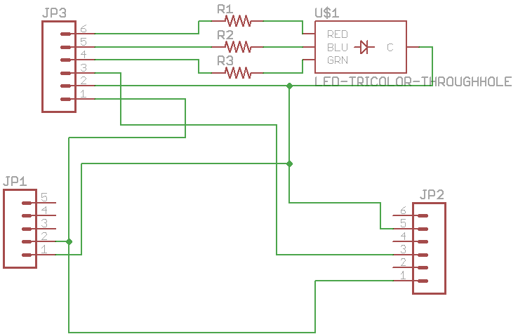
I have uploaded this code onto the ATMEGA328 and given it power. But it takes about 1-2 minutes for the program to reach the main loop. I think that this is the case because the first thing in the main loop is to turn pin 12 to HIGH. It take about 1-2 minutes (from when the power is switched on) for pin 12 to go high. I think that this is a problem with the code because I have been able to run code (that only turned on pin 12, that's it) and it worked fine. The circuit is in two parts (one part goes indoors and the other goes outdoors) and is on a pcb. Basically this is a rfid door lock system that sends information to a computer via an xbee network. I have attached images of the indoor and outdoor schematics as well. Anyway the real problem is that the program takes about 1-2 minutes to get into the main loop (At least it appears that way). Any help is greatly appreciated.