Hi.
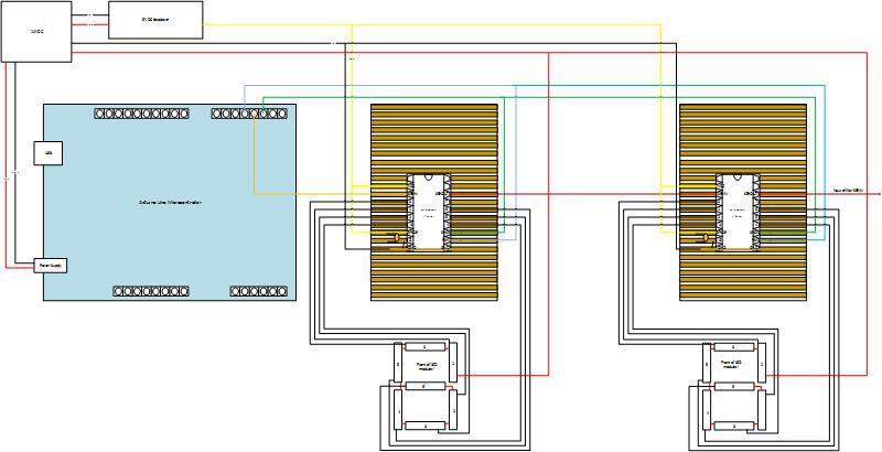
I am building a new scoreboard from 12 volt LED Strips. I want to use an Arduino with a TPIC6B595 shift registrar and 3 buttons to move the score up/down and a 3rd to return them to zero. There are 3 units. A triple digit a double unit and a single unit. I can manage the hard wiring. Its the code I am struggling with. I have tried to follow tutorials but find it a bit beyond me. Can anyone help me with a very basic code to do what I want. Which is press a button to increase the score, press another to decrease the score and one to set them all back to zero. I what to do this project and learn more about coding so may be in the future I can make it wire less.
I can't open your circuit diagram. I have built something similar for cricket. What exactly are you having trouble with. Please post the code that you have attempted.
i have had this problem in the past and i manged to do a 5 button version for 16x2 lcd and a nokia 5110 screen. send some pics then i will assist you with the coding.
please note if this is correct.
1 button gets pressed to increas score by one increment on a display.
another button is pressed to decrease scare by one increment.
when a certain number score is reached the display roles over to 0 or if a button is pressed for a set amount of time it resets the display to zero.
groundsman:
I can manage the hard wiring. Its the code I am struggling with.
If that diagram makes sense to you then you are a better man than I (well, even if it doesn't) ![]()
Anyway, you say you need help with the code but you have not posted the program you are having trouble with. I don't see how I can help until you do so.
...R
Hi,
I think a hand drawn circuit diagram with pin numbers and labels will be better.
Identify the cathode and anode of the LED strips and the size and type of power supply.
Thanks.. Tom.. ![]()
I still can't make out your circuit diagram clearly, but assuming that you have connected the TPIC6B595's correctly, you should start by seeing if you can make the numbers light up at all. Start simple and write out a bit stream that lights up one output at a time. Something like:
// Setup the stream of bytes to write to the shift registers
byte stream[SCOREBOARD_DIGITS];

stream[0]=1;
stream[1]=1;

// Eight bits in the shift register
for (int i = 0; i < 8; i++) {
  digitalWrite(LATCHPIN, LOW);
  for (int j = SCOREBOARD_DIGITS; j >= 0; j--) {
    shiftOut(DATAPIN, CLOCKPIN, MSBFIRST, stream[j]);
    // Shift the bit along 1
    stream[j] << 1;
  }
  digitalWrite(LATCHPIN, HIGH);
  delay(1000);
}
I leave code like this in my setup() anyway so that every time you turn the scoreboard on you can make sure that all the number segments are working, and it gives a pleasing little animation.
Once you get this working, setup some arrays that hold the correct outputs for each number from zero to nine. Something like:
// Output patterns for the digits from 0 to 9
const byte NUMBER[10] = {B01110111, B00100100, B01011101, B01101101, B00101110, B01101011, B01111011, B00100101, B01111111, B01101111};
Then when you want to display a particular number, you can write out that byte from the array to the bit stream i.e. to display a five you use NUMBER[5].
Once you get that working, you can move on to the buttons. There's loads of tutorials around for buttons as it's usually the second thing you do with an Arduino, after blinking an LED ![]()
Hi Davidrh.
Thanks for trying to help.I have never done any Ardunio coding before but want to try and learn, But I do find it very hard to learn without help. I was hoping to be able to find a code that had already been written for my project so I could look at it and work out the writing. So If anyone could help please I would be Grateful. I am not lazy and what other to do it for me just need gilding though it.
Eddie.
Hi Eddie,
Try the code that I gave you with your circuit and post back with the results. If you look at the code for a full cricket scoreboard it will just confuse you as:
- It probably doesn't match the circuit that you have
- It's doing quite a few different things
- It's probably doing some extra things that you don't want
It may seem like hard work to begin with, but you will learn a lot more by undertaking your project bit by bit and figuring it out as you go. It also allows you to post more focused questions that are more likely to get an answer.
Hi,
How much current is needed for each 12V strip?
What are the two power supplies?
Please a viewable circuit diagram.
Tom... ![]()
Hi
The LED strips are .5m lone and are 12v 8watts.
The power is 12v and 5v
I have tried to upload the drawing but cannot find a way to attach to the post. If you know how to do it please explain and I will try again.
So one 0.5 metre strip is drawing 666mA. What length are you going to make each segment of the numbers?
The TPIC6B595 can sink 150mA per output, so a little over 10cm will be your limit plus you are limited by the breaks in the strip where there are contacts for cutting it.
Hi,
groundsman:
Hi
The LED strips are .5m lone and are 12v 8watts.
The power is 12v and 5v
I have tried to upload the drawing but cannot find a way to attach to the post. If you know how to do it please explain and I will try again.
If you use REPLY rather than QUICK REPLY and it has an attachment facility at the bottom of the screen.
12V 8W So 8/12= 0.66A, what is the current capability of the TPIC6B595 ?
Tom... ![]()
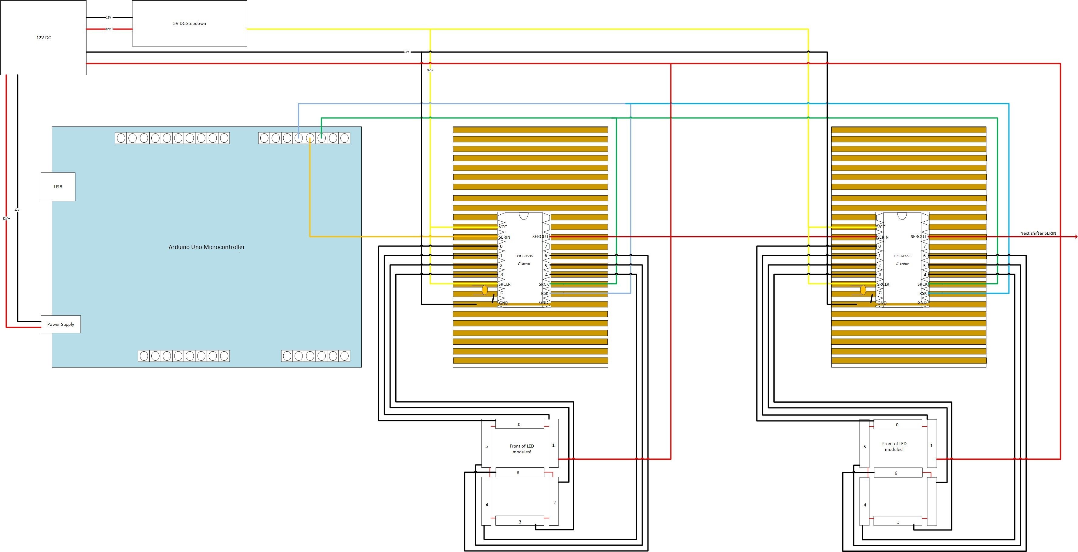
The other thing I have in my circuit is decoupling capacitors as close to the shift registers as possible. I use a 4.7uF electrolytic (1 per board of three shift registers) and a 0.1uF ceramic (1 per shift register). You put the capacitor between 5V and GND, taking care with the electrolytic that you get it the right way round.
Hi Davidrh.
In my drawing there is a capacitor between 5v and ground, but I don't known where you mean for the other one. Could you read my drawing better now? I was looking at the spec for the shift register and may be I am wrong but it said 500ma per output. Do I have to write you sketch out or is there a way to copy it to my Ardunio
Eddie
If you check the datasheet it says "Eight Power DMOS Transistor Outputs of 150-mA Continuous Current" which is what I was going on. That is with all outputs on, which you will nearly have when you display the number 8 as it uses all seven segments.
I didn't notice the picture of a capacitor on your diagram ![]()
groundsman:
Do I have to write you sketch out or is there a way to copy it to my Ardunio
You have to enter it (or copy and paste it) into the Arduino IDE. If you haven't used the IDE already, I would start with some simpler projects before your attempt your scoreboard. Have a look at blinking LEDs and buttons examples first.