Hi Everyone!
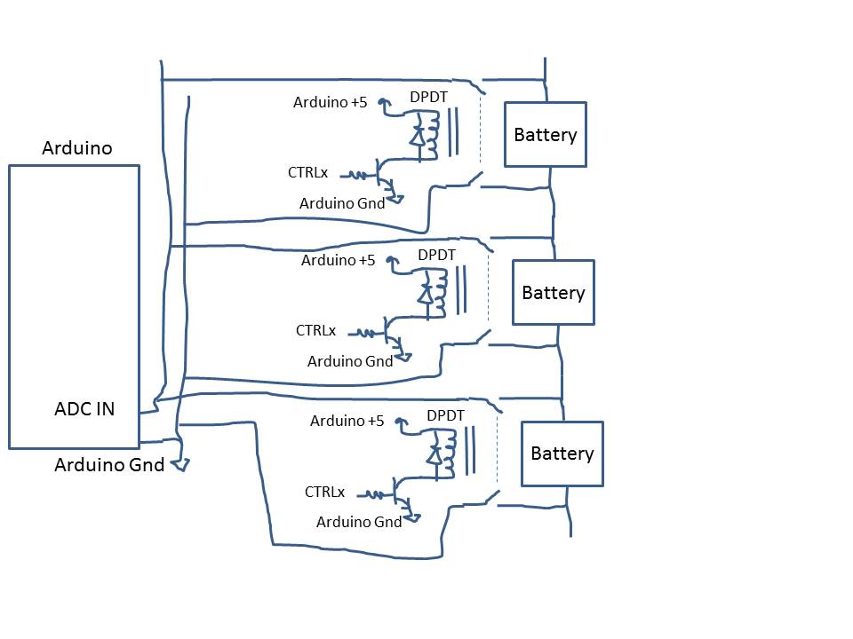
Project: attempts to very ACCURATELY measure the voltages of the series (and parallel) connected batteries.
NOTE: you may identify that their are some redundant connections to series batteries that are there so that the application can identify which are in fact connected in parallel and which in series and also it there are poor connections between the batteries.
You may also question the values and ratios of the voltage divider resistors.
These will likely change and are not my primary focus at this time.
A couple of comments on these.
1- because I may use 3.3v Arduino's I want to limit the voltage divider to 3.3v with some safety margin. Rather than use the Arduino's analog port I have tested and plan to use the ADS1115 16bit ADC but did not include it in the schematic in order to simplify things at least slightly. Of course, I'm open to ideas but have already tested with the Due analog read and the accuracy is almost but not quite as needed.
2- I would also appreciate input on if and how capacitors would allow higher resistance in the voltage divider circuit and still be able to accurately read considering that a voltage does not quickly change and an extra delay, an extra read or averaging is not a problem.
3- Since I am also concerned with the total current used in all these voltage dividers I'm wondering if there is a way to use transistors to turn on and off the dividers when they are going to be used or otherwise limit the current use when not needed and how to calculate the resistance of the transistor.
4- The main concern I have at this time is protecting the circuit or potentially redesigning a circuit that is more robust because it seems there are quite a few potential issues that can cause damage to the components. I've recently added the clamping diodes and an additional 100pf capacitor ( in addition to the .1uf) on the analog input line to help protect it but there still seems to be quite a bit of potential for disaster and I have had some. The worst seems to be damaged components that do not exhibit absolute failure but are degraded or intermittent resulting in bogus readings but not no-readings as I might expect or expected.
5- I'm considering and would like input on the following ideas and of course new ones please:
a fuses - Since I am primarily trying to protect against voltage, how can these help? How
to appropriately size and where to place them?
b is it possible to protect in case of ground disconnect? - when there is a disconnect or bad
ground connection the "divided" legs of the voltage dividers are no longer divided so can
surge - how can you protect against that?
6 Is there a better way to design the ground aspect of the connection? Is it possible
that there is current actually flowing "backwards" from some legs of the voltage dividers thru others because of the differences in voltages? would it be a good idea to add diodes here to protect against that? How can you calculate the resistance and impact on the voltage divider?
7 along this line, since some legs may have "designed" zero voltage - how to better protect against negative voltage? Hoping the clamping diodes will resolve this.
8 additional clamping diodes or similar on each voltage divider output to protect mux Is it best to use standard, schottky, or zener diodes and how? and how to select components? How can I confirm the current signal diodes are not "burned out"? When that happens how do you protect the other components?
9 how do clamping diodes not just redirect the spike or higher voltage to the positive rail and then fry the arduino thru the 3.3v (or 5v) connection and is there a way to protect against that?
10 optio-isolators - how badly would these effect accuracy of the voltage reading? what other negatives are there
11 what safety or circuit concerns would there be if this was part of a commercial product?
12 Is connecting the batteries causing surges? I think so. Should the mux and arduino be disconnected while the batteries are connected and disconnected and is there a way to do this electronically?
Of course, I would appreciate links or better ways to research these questions. I'm not looking for anyone to do the project but would certainly appreciate the ideas.