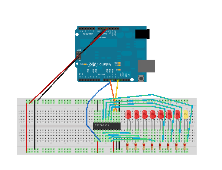
I'm having some difficulty working with a TPIC6B595 shift register. I am using this tutorial which supplied the following code and wiring diagram:
/*
 Shift Register Example
 for TPIC6B595 shift register by Jens C Brynildsen

 This sketch turns reads serial input and uses it to set the pins
 of a TPIC6B595 shift register.

 Hardware:
 * TPIC6B595 shift register attached to pins 7, 8, 11 and 12 of the Arduino,
 as detailed below.
 * LEDs attached to each of the outputs of the shift register

 Based on the example created 23 Mar 2010 by Tom Igoe

 */

//Pin to clear the register
const int clearPin = 7;
//Pin connected to latch pin (RCK) of TPIC6B595
const int latchPin = 8;
//Pin connected to clock pin (SRCK) of TPIC6B595
const int clockPin = 12;
////Pin connected to Data in (SER IN) of TPIC6B595
const int dataPin = 11;

int counter = 0;
int numLedsInUse = 8;

void setup() {
  //set pins to output because they are addressed in the main loop
  pinMode(clearPin, OUTPUT);
  pinMode(latchPin, OUTPUT);
  pinMode(dataPin, OUTPUT);
  pinMode(clockPin, OUTPUT);
  Serial.begin(9600);
  Serial.println("*");

  // Always start by setting SRCLR high
  digitalWrite( clearPin, HIGH);

  // delay a little and then set
  delay(100);
}

void loop() {
  // Display LED's running
  if( counter >= (numLedsInUse-1) ){
    counter = 0;
  } else {
    counter++;
  }

  // write to the shift register with the correct bit set high:
  registerWrite(counter, HIGH);
  delay( 100 );
}

// This method sends bits to the shift register:

void registerWrite(int whichPin, int whichState) {
  Serial.println(whichPin);

  // the bits you want to send
  byte bitsToSend = 0;
  // write number as bits
  bitWrite(bitsToSend, whichPin, whichState);

  // turn off the output so the pins don't light up
  // while you're shifting bits:
  digitalWrite(latchPin, LOW);
  Serial.println(bitsToSend);
  Serial.println("_");

  // shift the bits out
  shiftOut(dataPin, clockPin, MSBFIRST, bitsToSend);

  // turn on the output so the LEDs can light up:
  digitalWrite(latchPin, HIGH);
}
I am currently powering the Arduino via USB.
The behavior is that the rightmost LED will randomly turn on for a second or two and then when it does the other LEDs starting at the other end might blink very quickly going from left to right. Then it will be many seconds before it does it again but the timing is totally random and seems to be longer and longer between blinks.
From the video on the tutorial page it should be cycling through the LEDs on a much more regular pace starting at one end, blinking through to the other end and then immediately repeating without much pause.
Spent some time looking at this ... one difference to the original you link to is that he first raises the "clearpin" after the delay, you do it before. So the clearpin is low (after being set to OUTPUT it starts at LOW - meaning "active", negative logic) for only a very brief interval before you set it HIGH (meaning "inactive"). It should be long enough all the same.
You have put a bit of Serial IO in the registerWrite routine and that takes a long time (relativly speaking) but - again - it should not matter.
So the conclusion is you have not wired things correctly as the most likely culprit. Or blown the chip by a previous incorrect wiring (not as likely)
I actually only made the modifications in trying to start debugging it. So I have re-downloaded the code and am using it "as is".
I re-wired everything on another breadboard, double checked the diagram several times and even used another chip (I have 3 that I am planning on eventually chaining together).
I am still getting the same exact behavior.
As I mentioned before I am powering my Uno via USB, could that be the issue? I didn't think so because only one LED was being powered at a time. When I press the reset button all the LEDs light up but I assume that is simply because the chip isn't pulling them low during that time. I assume by that that the power should be sufficient.
Just to confirm that it is something on my end, did you test this or are you just using experience/knowledge to confirm that it should work? I don't mean that as an insult but I can't see anything that I'm doing differently and it's still not behaving as it should.
This is the first time I've worked with a shift register but from everything I've read it shouldn't be this difficult.
I noticed you left the output enable pin (/G, pin 9) disconnected. Try connecting this to ground. (It may not solve your issue, but it's good practice not to leave unconnected input pins).
ringz:
Isn't this the point where Grumpy Mike comes in to mention that you aren't using any decoupling capacitors on the supply pins
Martyn.
I'm honestly not sure what those are, I'm still rather new to the hardware side, my background is in programming. This is the only tutorial that I've seen using the TPIC6B595 that seemed to be complete. If there is anything wrong in it then it might explain why it isn't working.
fred256:
I noticed you left the output enable pin (/G, pin 9) disconnected. Try connecting this to ground. (It may not solve your issue, but it's good practice not to leave unconnected input pins).
I just tried connecting this and it made no difference at all.
I'm completely open to dumping all of this setup just to get something working. I have a project that requires the use of 3 chained shift registers but until I get a demo of one working there is no point in continuing on my main project.
So if someone can either point me to something that they know works or better yet post a working block of code and wiring schematic I'd be very grateful.
I have posted schematics in the past of multiple daisy chained shift registers using just this part. Instead of using shiftout(), I use SPI.transfer() to send the data out.
I generally tie SRCLR/ high, and OE/ LOW (i.e. they are not used), but I can see tieing OE/ to a PWM pin for brightness control
in void setup(){
pinMode (SS, OUTPUT);
SPI.begin(); // library takes care of D11,12,13
// etc.
}
in void loop(){
// say 4 devices being used
digitalWrite (SS,LOW); // SS (D9)goes to SRCK PIN on all devices
SPI.transfer(byte1); // SCK (D13) goes to clock pin on all devices
SPI.transfer(byte2); // MOSI (D12) goes to serial data pin on device 1,
SPI.transfer(byte3); // SEROUTfrom device 1 goes to device 2, etc
SPI.transfer(byte4);
digitalWrite (SS,HIGH); // outputs update on this rising edge
CrossRoads, looking at your short example and the Arduino SPI documentation it seems that SPI is the better way to go for what I want to achieve eventually. I have a couple of questions though.
First you state that D9 is the SPI pin but the Arduino SPI documentation states that "SPI bus uses pins 10 (SS), 11 (MOSI), 12 (MISO), and 13 (SCK)".
Next you stated "SCK (D13) goes to clock pin on all devices", the TPIC6B595 has no SCK, did you mean RCK? I guess they're probably technically the same across the different chips but since TI labeled it as RCK, I want to make sure I'm not doing something incorrect.
Using the diagram in the first post, I changed the Arduino Uno connections so that D10 goes to SRCK, D11 goes to SER_IN and D13 is going to RCK. I have Vcc tied to 5v and the three GNDs tied to ground. Nothing is connected to SRCLR.
Here is my current code:
#include <SPI.h>

void setup() {
  pinMode(SS, OUTPUT);
  SPI.begin();// library takes care of D11,12,13
}

void loop(){
  // say 3 devices being used
  digitalWrite (SS,LOW);  // SS (D10)goes to SRCK PIN on all devices
  //SPI.transfer(byte1);  // SCK (D13) goes to clock pin on all devices
  //SPI.transfer(byte2);  // MOSI (D11) goes to serial data pin on device 1,
  //SPI.transfer(byte3);  // SEROUT from device 1 goes to device 2, etc
  digitalWrite (SS,HIGH);  // outputs update on this rising edge

  // check if byte1,2,3,4 need update
  // etc.

}
When I upload this the behavior is that the right most LED is constantly on. I wouldn't expect this as I'm not currently sending anything out via SPI.transfer. If I change the commented SPI.transfer(byte1) to send a value of 0-255 the rightmost LED is still constantly on and nothing different happens.
Yes, SS on D10, not sure how 9 snuck in - miscounted I suppose.
Connect SRCLR to 5V. Or drive it high with an arduino pin.
Connect OE/ to Gnd, or drive it low with an arduino pin.
Put a 100nF/0.1uF cap from 5V to GND.
D13/SCK goes to SRCK on the shift register.
D10/SS goes to RCK on the shift register.
D12/MOSI (unless D11 is MOSI) goes to SERIN. SEROUT goes to the next chip in line.
Thanks for the reply, glad I'm at least starting to get this...
You said "Connect OE/ to Gnd, or drive it low with an arduino pin", I don't see an OE on the datasheet. Forgive me if it is a standard term, my background is in programming.
I don't have any 100nF/0.1uF caps right now, is it critical for this to work or is it more for balancing?
Will these work? I'm trying to get stuff locally as shipping and customs taxes are ridiculous in Sweden.
Capacitor 100nF 50V Y5V axiell
Multilayer ceramic capacitor.
Tolerance 20% on
The body size 2.5 x 4.3 mm.
Suitable hole interval 5 mm.
Bendiameter 0.5 mm.
I've received the caps but I'm not quite sure where to place them in my current layout. I'm thinking that I may need to change the power/ground layouts on the board for them to work correctly?
#include <SPI.h>

void setup() {
  pinMode(SS, OUTPUT);
  SPI.begin();// library takes care of D11,12,13
}

void loop(){
  // say 3 devices being used
  digitalWrite (SS,LOW);  // SS (D10)goes to SRCK PIN on all devices
  SPI.transfer(0);  // SCK (D13) goes to clock pin on all devices
  //SPI.transfer(255);  // MOSI (D11) goes to serial data pin on device 1,
  //SPI.transfer(byte3);  // SEROUT from device 1 goes to device 2, etc
  digitalWrite (SS,HIGH);  // outputs update on this rising edge

  // check if byte1,2,3,4 need update
  // etc.
}
No matter what value I put in the SPI.transfer() it still only lights up the last LED and it is also lighting up the LED on pin13 on the Arduino Uno itself.
It's late and I'm sure I'm just missing something simple, hoping anyway.