Can someone explain to me what the code in this example:
http://www.arduino.cc/playground/Learning/4051
is doing?
I can program, but I do not understand what exactly this program is doing.
Thanks,
Riley
Can someone explain to me what the code in this example:
http://www.arduino.cc/playground/Learning/4051
is doing?
I can program, but I do not understand what exactly this program is doing.
Thanks,
Riley
The short story is that the binary numbers 0 to 7 (000 - 111) is written to the 3 digital pins 2, 3 and 4.
This is done to addres the A, B, and C input on the 4051 to selct input 0 to 7.
The reason it s hard to understand is that they use some bitshifting to make the program fast and short.
Yes, it is a bit difficult to understand.
The part I am mainly missing is how to read the analog input from this signal.
It seems like this part of the process is left out, which is a bit strange.
How would I go about reading the values of the input selected using the sample code?
Thanks,
Riley
Yes, you are right that part has been legft out.
You connect pin 3 from the 4051 to an analog pin on Arduino and do an analogRead() where the serilaPrint comment is in the code.
And this will return the value of the input currently selected by the count variable?
My god! This is so frustrating!
I've spent hours testing this thing out, and still have had no success.
As far as I can tell, from your advice about the analogRead, doing so will read the value of the input selected using the count variable.
But this does not seem to be the case.
What am I missing?
Have you connected Arduinos ground to the 4051's ground ?
What are you trying to read from the 4051 ? potentiometers ?
How is it hooked up ?
I have some code on another computer that i can't get to right now, it uses 2 4051's to read 16 slide pots, i can send it to you sometime tomorrow.
EDIT and did you connect the Enable pin (6) to ground ?
Yes, I am trying to read 8 potentiometers for a midi sequencer project.
For the moment, I have the circuit built with just one of the inputs hooked up to a pot.
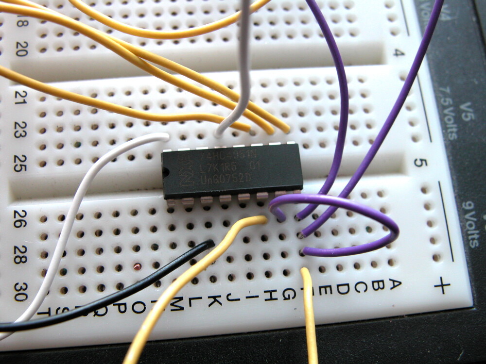
Here is a photo of the wiring:
The black wire goes to analog pin 4.
One of the purple wires brings ground to the chip, from the arduino. The other purple wire that heads into the northern part of the photo is for ground to the potentiometer that I have hooked up to y0.
The yellow wires that you see at the bottom are actually just one wire, which connects those two pins of the chip together (ground).
The white wires are input (in the center) and 5v in from the arduino (on the left).
Is this correct?
You must connect the enable pin (6) to ground
At the bottom of the picture, you can see two ends of one yellow wire. They connect pins 8 and 6 together.
Wouldn't that work?
Is the pot hokked up as a voltage divider, like:
5V to one side pin, center pin to y0 on 4051 and other side pin to ground ?
Do you get any readings at all from the analogRead() ?
that should be ok pins 6,7, and 8 should be grounded AND connectd to ARduinos ground
Yes, the pot is configured that way. I do get a reading, but it does not seem relevant at all to the input I have selected.
What I mean is, I want to read just input one, and I can't figure out if it's doing that or not.
This code, for instance:
/*
codeexample for useing a 4051 * analog multiplexer / demultiplexer
by david c. and tomek n.* for k3 / malm? h?gskola
*/
int led = 13; //just a led
int r0 = 0; //value select pin at the 4051 (s0)
int r1 = 0; //value select pin at the 4051 (s1)
int r2 = 0; //value select pin at the 4051 (s2)
int row = 0; // storeing the bin code
int count = 0; // just a count
int bin [] = {000, 1, 10, 11, 100, 101, 110, 111};//bin = bin?r, some times it is so easy
// int inputarray[8];
void setup(){
pinMode(2, OUTPUT); // s0
pinMode(3, OUTPUT); // s1
pinMode(4, OUTPUT); // s2
digitalWrite(led, HIGH);
beginSerial(9600);
}
void loop () {
digitalWrite(led, HIGH);
for (count=0; count<=7; count++) {
row = bin[count];
r0 = row & 0x01;
r1 = (row>>1) & 0x01;
r2 = (row>>2) & 0x01;
digitalWrite(2, r0);
digitalWrite(3, r1);
digitalWrite(4, r2);
//Serial.println(bin[count]);
delay (analogRead(4));
digitalWrite(led, LOW);
}
}
allows me to use the potentiometer to blink the LED.
But what information is the analog input receiving?
If I change 'count' to be a static number '1' instead of cycling, it does not input the value of the pot.
does the blink rate change if you torn the potentiometer ?
The analogRead should return a number in the 0 - 1023 range 0 when the pot is all to one side and 1023 when it's all to the other side.
Try changing the loop to this, and enable the serial monitor in Arduino
void loop () {
for (count=0; count<=7; count++) {
row = bin[count];
r0 = row & 0x01;
r1 = (row>>1) & 0x01;
r2 = (row>>2) & 0x01;
digitalWrite(2, r0);
digitalWrite(3, r1);
digitalWrite(4, r2);
Serial.println(analogRead(4)/4);
delay (200)
}
This should write 8 bytes to the serial monitor, the first from your pot, should give you values between o and 255 when you turn the pot.
The other 7 could be anything since they are from the 7 pins on the 4051 with nothing connectd to them.
I'm of to bed in a second, it's very late over here ![]() but i will chek up tomorrow.
but i will chek up tomorrow.
If I change 'count' to be a static number '1' instead of cycling, it does not input the value of the pot.
The array is 0 based so that count should be 0 if you do that
I will try the things you mentioned, and I'll let you know how it goes.
Thanks very much for all your help!
I'm interested, because I want to use this mux, but the sample code doesn't seem very complete... can you tell me how it works now and your current code?
Thanks!
Just in case anyone reading this needs more analog inputs, I thought I'd pass on a hint that I gleaned from the BeatBearing project in Make (Volume 17):
That device uses a HEF4067B analog multiplexer with 16 inputs. It's a Philips (now NXP) part:
http://www.standardics.nxp.com/products/hef/datasheet/hef4067b.pdf
Has anyone used this chip in a similar circuit to the 4051 setup?
I don't get any of this...
I want to read 25 LDR's but first I can't get it to read anything.
Here is how it is wired:
5V - LDR -|y0   s0|-  D5
          |y1   s1|-  D6
          |y2   s2|-  D7
          |y3     |
          |y4     |
          |y5     |
          |y6     |
          |y7    z|-  analogInPin
What am I doing wrong? And what is the correct code to read the inputs?