Hi guys!
I'm trying to interface an old Seeburg Wallbox with my Arduino. The Wallbox sends a timed signal using 24VAC. My idea was to grab that signal using an optocoupler, since, to me, it seems like the best way to isolate the pure-AC circuit of the Wallbox from the pure-DC circuit of the arduino.
My question would be if anyone of you knows about an optocoupler that can handle 24VAC at 2A max. (I doubt it'll ever reach the 2A, but it'd be nice just to be safe) on the LED-side and the default 5VDC of the Arduino on the transistor side?
What is a Seeburg Wallbox? You won't get 2A through an optoisolater.
Is it a power supply because you can't transfer power through an opto isolator only signals.
I'm trying to interface an old Seeburg Wallbox with my Arduino.
Yes, right resistor and a diode in series to block the reverse 24VAc should work... The peak voltage of the waveform will be about 34 volts (24 * square root of 2?); use that in picking the resistor to put about 20 ma through the optocoupler LED. Almost any Optocoupler should work..
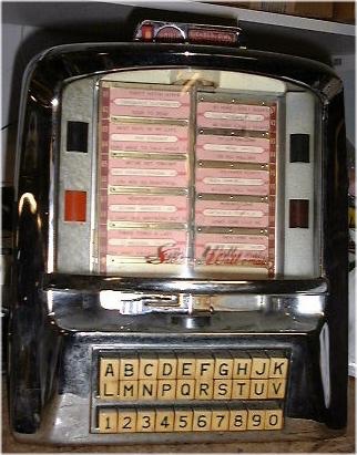
These wall boxes (as seen in thousands of USA Diners, years ago) received coins and button pushes and drove mechanical relays in the JukeBox music player.
As I recall they drove "stepper switches" in the jukebox to select the record to be played.
I think there are some discussion groups online that know a lot about these; Google Away...
I've just been to my local electronics shop and they've told me that an opto-coupler won't work at all for this.. kinda strange.. The man said something along the lines that
a) There's no opto-coupler that allows AC on it's LED (makes sense now that I think about it..)
b) When simply using a resistor and diode to only get the +24V-0V part he said the signal would get "distorted", which has something to do with the waveform of the pulse.
Thing is.. can't I just "recalculate" the correct signal in my code? I know that the pulses are seperated by something between 300-500 milliseconds, so I guess that there should be enough room to detect a "gap" in the signal and make out where one pulse begins and ends, right?
Perfect! Yes, knowing that there IS a signal is enough for my project. Essentially, I want to check if there's a signal (haven't decided whether to use interrupts or loops yet) and if so, check the time between the current and next signal. There's an exact combination of signals for each title selection you can make on the box. I'll then send these via bluetooth to my PC/Laptop/etc. to play an according tune
I've just read about diode bridges/bridge rectifiers. Would it also be an option to convert AC to DC using a diode bridge like this one (File:Diode bridge alt 1.svg - Wikipedia) and then run the output DC through a regular opto-coupler?
Tbh, I have no Idea.. my multimeter isn't accurate enough to measure the pulses in time, so my best chance of finding out when exactly the pulses fire is by hooking it up to my arduino constantly checking its input.
It basically works like this:
There's letters (A-V, omitting some like O or I) and numbers (0-8), making a total of 160 possible selections. When a combination of Letter+Number has been pressed, a motor moves a contact arm first over numbers 1-8. The contacts are wired in series, so if I'd press 5, pulses would be fired when the contact arm went over 1,2,3,4 and 5. Same thing then happens again for the letters, with a longer pause in between to detect the transition from number to letter.
Documentation on these machines (especially on the parts you usually wouldn't have to worry about when hooking it up to a regular jukebox) is quite hard to find, so unfortunately I haven't yet found anything about the pulse timing..
So you really need some more data before you can decide exactly how to do it but it sounds like in the end you don't need do anything clever, just count a few pulses.
Before you can do that you need the timing information so yes you're on the right track if you don't have any proper test gear.
All you need to know is the gap between each number/letter in a burst of AC pulses and and gap between the two groups of bursts.
So I would rig up the opto as we've been discussing (with or without a bridge, as this is mechanical it will be slow so the double resolution shouldn't be needed but won't do any harm) and run the pulses into an Arduino external interrupt.
You could also just use a diode or bridge and two resistors forming a voltage divider.
Either way it may also be necessary to clean up the sine wave (assuming that's what it is) with a Schmitt trigger or a comparator with some hysteresis.
In the ISR simply save the millis() value into an array.
When the sequence is finished print the values to the screen and analyse them. Each reading will be the (say) rising edge of a pulse so you will easily see the patterns. Put the values into Excel and do a graph or calculate the time between each reading .
Hi Rob!
Thank you so much for helping me out this detailed
Apparently so, yes. From the looks of it I can't seem to find anything more complicated to the mechanism than this - considering it's a consumer machine from the late 50's, this might even hold true.
Since it's a cheap part, I'll additionally use the rectifier bridge. If the Schmitt-Trigger is needed, I'll add one, but for now I'll try with as few parts as possible to not make it too complicated for me.. been a while since I've fiddled with electronics
Yea, that's pretty much what I was planning to do. Then once I have the correct sequences, it'll just be a matter of deciding on which device to decode them. I'll probably do it on the arduino, since I'm not too sure about sending time-critical data via bluetooth, although after some tests it shouldn't really matter.
As for the opto-coupler itself, I've been looking at this one:
That opto seems to need 20mA forward current which is a lot but that doesn't matter here.
Terry had the voltage numbers above, I'd use the Vf of 1v2, just under the max of 50mA (say 45) and the peak V for the LED current calcs, it doesn't matter at what point in the waveform the LED turns on.
As you say try without cleaning the pulses, if there's a problem either add the Schmitt trigger or debounce in software.
BTW I just love the idea of a 50s jukebox controlling a PC/iPad etc.
These look really nice! I just found out that there's a german version of Digi-Key as well Before it would've been quite annoying having to wait a couple weeks for your parts to ship from the US, so I generaly avoided any US retailers..
@GoForSmoke: Thanks a lot for these links as well! I'll be sure to check them out.
@Graynomad:
I've had the idea for a while now, but unfortunately it's quite hard to find an original Wallbox/Jukebox over here in germany at a reasonable price. I bought the box for around $200 and I must say, for that price it was a steal! The box was alomst entirely in original condition, except for the lamps, coin slot and the "Make any selection" plates, which had been replaced by cardboard with german text on them. Oh yea, there also is a german slug rejector in there (wouldn't make sense to only allow USD in Germany, huh :D)
I've replaced all the parts and quickly hacked together a power plug for a 24VAC transformer I found on eBay. The big surprise came when I first hooked everything up.. it went pretty much perfect on the first try. There's a couple of adjusting screws you'll have to take care of, because obviously they'll have losened over time, but otherwise it worked just fine
If anyone's interested in a couple pictures of the rebuild-process, here you go
BTW that page hardly works at all with Safari 5.0.5, the thumbnails just show the top few pixels and the photo the right few, I had to click on the view full res magnifier to see anything. See attached.
