Hi, I'm having trouble getting to work a couple of MAX7219. I tested the circuit on a breadboard and it worked perfectly, then I soldered all the anodes and cathodes to the MAX7219's to a perfboard and tested them connecting the Data In, Load, Clock, 5+ and Gnd to the Arduino with alligator cables and worked fine but then I soldered them and nothing lights up. I've checked everything for an hour but all seems to be ok. I really have no idea what's gone wrong. The arduino is powering the circuit and the drivers are receiving the voltage they need.
This is the code I'm using to test the matrix. I'm using 2 drivers but for testing purposes I'm just trying to control one. It's pretty basic.
#include <LedControl.h>
LedControl lc=LedControl(12,11,10,1);
void setup()
{
lc.shutdown(0,false);
lc.setIntensity(0,8);
lc.clearDisplay(0);
lc.setLed(0,0,0,true);
}
void loop()
{
}
I don't know if it matters that I didn't use the capacitors though when testing on the breadboard it worked well without them.
Do you have any suggestions where I should check the circuit? I think I just broke my brain or something trying to figure out what's wrong but I can't find anything. Thanks in advance.
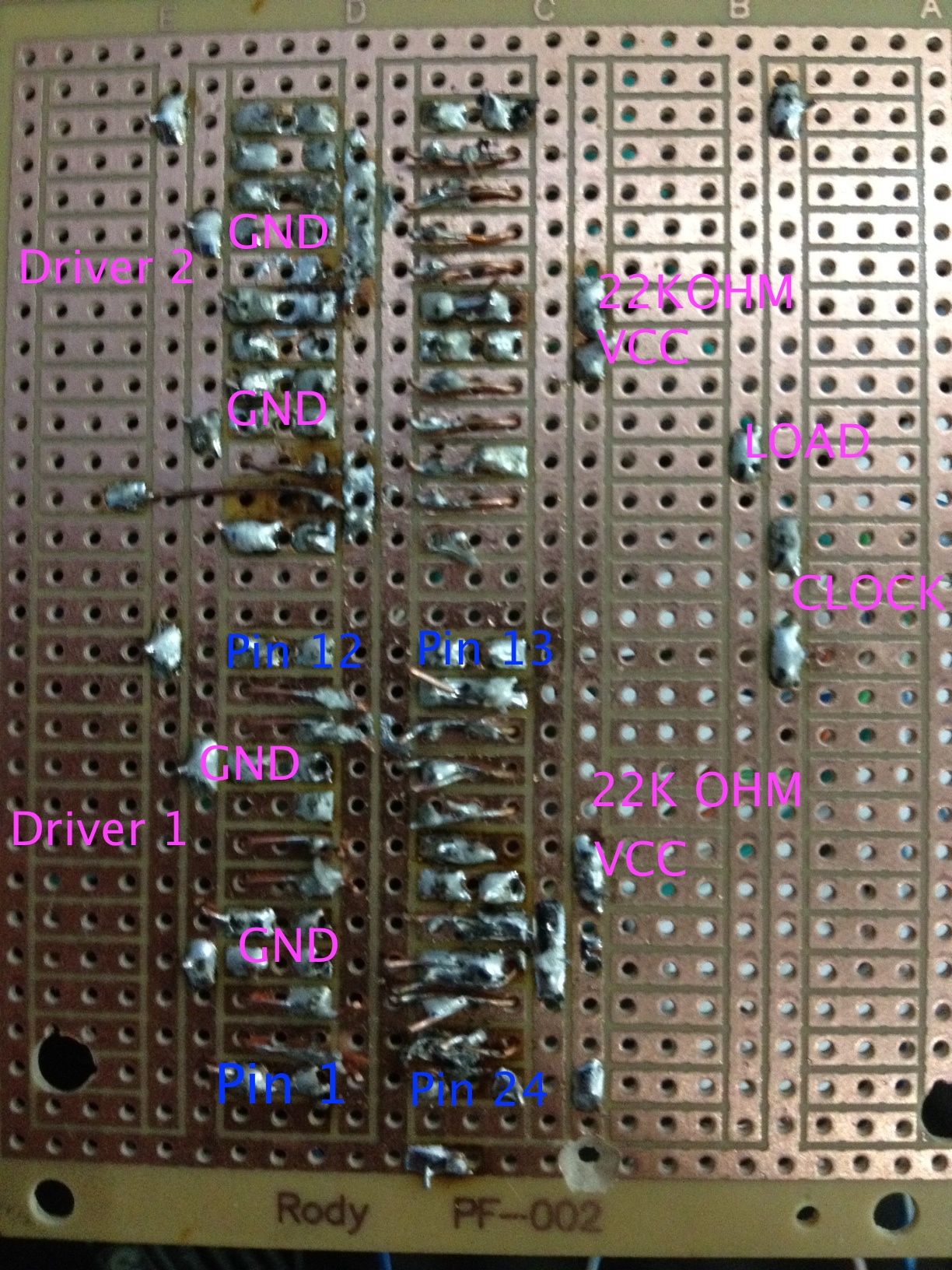
I'm attaching a picture of the back of the circuit. Maybe it helps. This is the first time I've soldered so perhaps something is not soldered correctly. I just don't know. There's also the diagram I'm using from the Arduino page.
This is the first time I've soldered so perhaps something is not soldered correctly.
Yes, that is a workable hypothesis. You should trim the leads short so they don't spill over the edges of the copper and short other things out. It's hard to tell from the photo, but I strongly suspect you have soldering issues.
Try checking the connections with a multimeter (eg. one that beeps for continuity). Check not only that things are connected where they should be, but are not connected where they should not be. For example, check that 5V and Gnd are not connected.
It is hard to say from the pic, but id guess i can see some cold solders there anyway. Another thing, if the caps were on the schematic, then you should use them. Might work for a couple minutes, but doesnt mean that will not blow something after a while on. wouldnt be the firsst nor the last time.
Definitely keep the caps in. The tutorials I read on arduino playground to get me started using this chip said they were required and should NOT be left out. I've always used them as instructed and have not had a problem so far.
And that's why I wirewrap ...
Thanks everybody. I'm doing everything again. I still don't understand where do the capacitors exactly go in the circuit or what are they for. I'd appreciate if anybody could make this clear for me.
That was an exceptional picture of the bottom side of the 'board', I can't (in 40 years) remember when I ever saw it's equivalent.
On the other hand however good soldering is as much in the technique used as it is in the materials used. It is a form of artwork
and Pre-tinning the leads would have done wonders as would a 'cooler' soldering iron. I use an old Hakko 926 and rarely turn it above
650 Deg F.... Unless I have a large repetitive soldering task to do, like those .040 pins and sockets used for interconnects and jumpers.
Capacitors for bypassing noise are the MOST frequent mistake made in ANY design. My own experience is that some heavy stuff at the
PSU input and a .1uF & 1uF ceramic used on each board powered from the Uno is sufficient. Drawing more than 100 mA from the Uno
regulator is also a BAD idea as the currents flowing to the 'external' board also flow in the Uno's ground circuit and WILL cause unusual issues
to crop up ( like mushrooms after a rain). If the Power supply is noisy due to external loads so are the (for example) A/D inputs going to
be 'noisy' as well and a cause for concern in digital transfers (IIC and SPI) as well. They can cause random errors that are most difficult to find.
Doc