Hi,
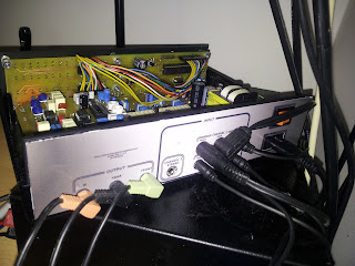
I just want to share my last project I did.
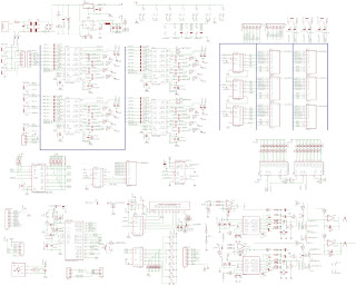
see http://electronprojects.blogspot.ie/p/arduino-atmega328.html for arduino code & schematics + layout
What is in it:
AtMega328P-PU with Arduino bootloader
4x TDA7439DS Audio stereo processor with digital interface (4channel multiplexer, Bass, Middle, Treble, Volume, Gain, Attentuation)
6x HEF4051 analog Multiplexer for output channel Remapping
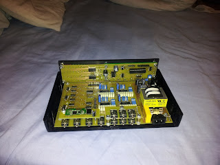
2x PT2399 surround processor
1x PCA9545 I2C switch
74HC595 shift registers
MCP4261 digital pot
20x2 LCD display
A2DP Bluetooth receiver
TSOP38238 IR receiver
2x TLC5925 + 32LEDs for VU meter
and more...
What it can do:
I wanted to build an audio mixer for my computer speakers with channel remapping (my computer is on a side of the room) and room correction. This can map any input to any output, has build in Gain, 3 band Equalizer, Room correction, surround module, Volume, Attentuation, Remote controller receiver, 4channel VU meter, LCD display, it can play simple sounds (Tone library) and has 2x 5.1 input, stereo input and build-in bluetooth receiver.
Description of operation:
TDA multiplexer will select one input channel:
Channel 1: 5.1 input (computer) - Front, Rear, Center + Woofer
Channel 2: 5.1 input (Media Player) - front, Rear, Center + Woofer
Channel 3: Stereo input (TV) - Front, Rear is wired to front, so is Center + Woofer
Channel 4: A2DP Bluetooth receiver (Bought on eBay, mapping same as with channel 3)
Next is GAIN (+30dB) for quieter inputs
Arduino Tone Output is connected using analaog multiplexer to Monitor on all TDA's. It is also connected to Arduino Analog pin to monitor Voltage Levels for VU meter
TDA then has Volume (-79dB) , Bass, Middle, Treble (+-15dB) and attentuation Left & Right) (-79dB)
After TDA's there is 6 HEF4051 8 channel Multiplexers that will direct ANY channel to ANY or multiple Speakers (Output from TDA is around 4V - it has internal op-amps, therefore the 4051 is working at around middle range with power 9V)
(Rear left can become front right, front right can be front left ... any way you want)
From the rear speakers the signal goes also to the Surround Board (with two PT2399) and they can be turned on and mapped to surround speakers.
Another Function is STEREO - on 5.1input channels, it can direct front inputs to rear speakers to Fill the room in case rear input is quiet.
Controls:
Menu button, 4 channel select, UP/DOWN + Select buttons are on the front panel
When you're not in Menu, UP/DOWN is Volume, SELECT will turn on Night Mode (LEDs are OFF, LCD is dimmed).
Whole unit is controlled with universal remote (NEC protocol) and has quite messy but working custom interrupt driven IR procedure with address and command (+ verification).
Everything is displayed on 20x2 LCD display and 4x8 LED Vu meter with animation if signal isn't present
Menu Items:
Mode - Select 5.1 or stereo operation **
SubWoofer - BASS adjustment **
Surround - ON/ OFF **
Equalizer - 6 presets + CUSTOM (every channel individually)**
Channel Remap - This is where you will set speaker placement (eg Front Left -> Rear Right)
Gain - gain settings (for input volume level correction)
Surround Settings - 4 settings of Surround module - DELAY
Room correction - Every speaker can be attentuated up to -79dB
** - dedicated Remote buttons
Remote also has:
Volume Up / Down
Bass Up / Down (Woofer only)
Channel Select
Night Mode
MUTE
IR setting:
If you want to assign address and commands form remote, change debug constant from 0 to 1 and the unit will switch into IR check and will display all codes received on the LCD display. With them codes you can then assign functions to buttons (constants again)
Other:
All TDAs have the same I2C address, I used PCA9545 I2C multiplexer
To save some pins - 8 to 3 encoder is used for the switches
and LCD is driven with 74HC595 shift register so are all HEF4051 analog multiplexers and TLC5925 LED drivers - everything with SPI @ 8Mhz (clock / 2)
Switch and IR decoding has its own Interrupt routine (speed) and all other procedures are prioritized in the LOOP
All settings are stored for each input individually (Volume, Mapping, Equalizer ...) and restored every time the input is changed.
All settings (except for volume) are written to EEprom on every change and restored during startup
In original design there was an opamp that was connected to the VU input, but didn't work (bad design) and was replaced with decoupling capacitor (updated in schematics). For better VU acquisition it should be re-designed and added, for lower signals
tone library is used to create sounds (button push, max / min volume or settings)
Quality of sound: I'm not an expert, but I would say great. No noise, perfectly quiet if no signal is present, no interference, no sound (like a bang) if channels are changed, equalizer is working beyond expectations, just great (I'm sure someone will say it can't be because ... )