I am looking for a calculation to match a resistor network. I want to be able to measure the voltage of "n volts".
The setup is like this:
n volts
|
r2
|
ADC---r1---4.7v
|
r3
|
Gnd
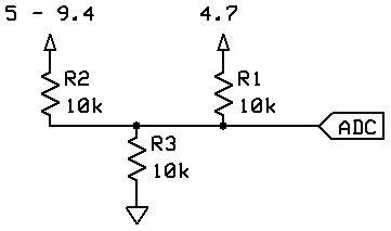
n volts will be 5 to 9.4 volts.
r2 and r3 can be whatever. I would probably go with 10k for each.
r1 is 10k.
the ADC is 10-bit, and the voltage range is 0 - 4.7v (so the voltage cannot exceed 4.7v).
So assuming all resistors were 10k, how would I calculate the voltage of "n volts"?
r1 doesn't look to me like it will affect the voltage, so r2 and r3 act as a voltage divider, halving the voltage n, so to get a maximum of 4.7, n could be 2 * 4.7, namely 9.4V.
Yes, you only require the two series connected resistors wired as a simple voltage divider. An analog input pin is a high impedance input and can and should be directly wired to the junction of the two resistors. Your R1 serves no useful purpose and only raises the source impedance of the signal to be measured, which is not a good thing.
I know all of that, but r1 is fixed, and there is no reasonable way to remove it. This isn't for the Arduino, it's for the Lego NXT (and it has built in 10k pullups on the analog lines).
See only now do you tell us the vital bit of information, so only now are we in a position to supply a sensible answer!
You need to apply kershoffs law, the sum of all currents into a node is equal to the sum of currents out of a node.
So if your potential divider has 10K resistors, with a voltage n, then into the node at the analogue input you have a current of
n / (10K + 10K) = 0.05n mA
Add a resistor of 10K to a 4.7V reference voltage, then the current through that will be defined by the voltage across it. This is 4.7V - n/2 so will contribute:-
(4.7 - n/2) / 10K
This will then add to the current flowing down R3 and increase the voltage across it, raising the current at the node and thus lowering the current contribution of R1.
So you can work this out by iteration, or by calculus, or in fact you could just measure it.
Sorry, I thought I made the setup clear in the first post... The application isn't specific to NXT, it applies to any ADC with a fixed 10k pullup to a mid voltage.
So, I'm still not really sure exactly how to compute it. Do you think you could help me out a bit more?
There is an important theorem about resistor networks:
Any node in any network of fixed resistors connected only to fixed voltages behaves as if its connected to a single resistor connected to a single voltage.
Thus the combined effect of R1, R3 and the 0V and 4V7 rails is to simulate a single resistor connected to a single voltage between 0V and 4V7. So you have a voltage divider (when combined with R2) that can't go below the "single voltage". If R1=R3 then that voltage is 2.5V.
So you don't want R1 if you are going to make full use of the ADC's input range.
I don't mean to be rude in the slightest, but R1 is not optional! I have no choice of removing R1 from the equation, so I need to find an equation that takes all three resistors into effect. I would go without the equation before suggesting people open their NXTs and remove parts from the PCB... it just simply won't happen.
I really appreciate you all trying to help, but if what you all are saying is that there is no equation that any of you can come up with, I will look elsewhere for the answer.
Well if R1 and R3 are already fixed there's nothing you can do, but calculating their equivalent circuit is easy - their equivalent voltage is calculated by assuming R1 and R3 form a resistive divider, and their equivalent resistance is as if they are in parallel (R1 x R3) / (R1 + R3)
That equation gives the value of r1 and r3 in parallel, which they are not. Doesn't the fact that r3 is pulled down 4.7 volts further than r1 make a difference?
...r2 and r3 can be whatever. I would probably go with 10k for each.
r1 is 10k...
...So assuming all resistors were 10k, how would I calculate the voltage of "n volts"?
With the only voltage source defined in the circuit is the +4.7 from the pull-up on R1, then a DVM meter measuring point 'N' will read +2.35, assuming all resistors are 10K ohms.
R1 and R3 form a simple voltage divider cutting the voltage down by 50%, R2 will have no effect if measuring the voltage at the top of R2 assuming a standard volt meter impedance of 10 megohms.
But somehow I don't think that is what you are looking for, as I don't think you have stated the 'problem' correctly or completely. Is point 'N' is going to be a source of voltage input into the network, or a measurement point only?