I have a need to control a 5v input with a 3.3v output. I did some research about level shifting, and there are many ways to do it.
I grabbed some random parts that I had laying around and made something work, but I am not sure if it is a good idea to implement in a final product.
Usually an NPN transistor is used to take a load to ground, and I have used one for level shifting when taking the higher voltage to ground using the lower voltage on the base.
What I have done here is basically opposite of that. I have put the NPN upstream of the MCU and I am using it to pull the pin HIGH. My question is whether this is a bad idea to connect the tansistor in the follwing manner:
emitter to a 5v MCU input
base to a 3.3v MCU Outputf
Collecter to +5v
It DOES work, but it might be a bad plan long term. My other method would be to use a PNP and NPN pair, using the NPN to take the PNP base to ground, and the PNP would supply the high signal to the 5v. Is this a better method?
I've just been wiring the 3.3V output directly to the 5V input pin. I have several purchased shields that also take this approach. The 328 chip specifies a minimum of 0.6*Vcc for logic high level. For 5V that translates to 3.0V so a 3.3V output makes the cut. It seems to work...
I have done that in some cases, but this needs to be very reliable out in the field. I would prefer to have a higher buffer margin there, especially considering that the power supplies are separate. If it ever did cause problems, chasing down the issue would be nightmarish. Also, I already have to have some level shifting components in this same box, because on other pins I have to take a 5v signal to ground. I cannot sink 5v through a 3.3v MCU, so I already have transistors in play here. For that I am using the same NPN, but in a more normal connection.
So basically, you are correct, and it would PROBABLY work with no issues, but I would rather be safe than sorry.
Also, I am not actually using the 328, I am using a 5v ATtiny2313, a 5v PIC16C620A, and a 3.3v MC9S08QE3.
I promise I am not choosing to integrate these three platforms together just because I am a special kind of masochist, I truly don't have a choice on the hardware, I just have to make it work.
I'm pretty sure the ATtiny has the same input characteristic. I don't know about the PIC; for sure you'd want to check that. But if reliability under adverse conditions is paramount then why not use a dedicated level shifting chip and sleep well at night?
jboyton:
I'm pretty sure the ATtiny has the same input characteristic. I don't know about the PIC; for sure you'd want to check that. But if reliability under adverse conditions is paramount then why not use a dedicated level shifting chip and sleep well at night?
Both the PIC and the ATTiny have the same 0.6Vcc spec. I SHOULD be fine. And this may be the route I go...
Do you know of a nice dedicated 3.3v --> 5v level shifting chip that doesn't use a pull-up on both sides? I came up empty.
ianahner:
Can anyone confirm that an NPN PNP pair would work? Could I use the NPN to pull the PNP base to ground, and then let the PNP supply 5v to the MCU?
Yes, this is the standard way to use PNP or P-chan fets (which have the analogous problem) to switch voltages higher than the signal you're switching with.
And yeah - there are level shifter chips that have it all done in one neat little package (they work much the same way).
HA! Wow... I knew I was missing something. So I didn't gain anything, and was simply switching it with the 3.3v.
In fact you actually lost 0.7V. The output on the emitter will not get any bigger than 3.3 - 0.7 = 2.6V
So if it works off that you could connect it directly.
I agree, the 4049 or 4050 works fine as a level shifter. Connect VDD to the desired output. So if the input is 3.3V logic and the output 5V logic, connect VDD to 5V. If inputting 5V and outputting 3.3V, connect VDD to 3.3V.
Otherwise, if you only need one, an NPN and PNP works fine for this. As far as pull-ups go: The input of the level shifter is driven by the 3.3V logic, so it is what it is. But on the output, something has to act as a pull-up or pull-down so it isn't left floating.
I didn't realize it was obsolete. It came with a 3.3V display I purchased fairly recently. The one I have is actually an NXP part and is, in fact, discontinued.
Those 16 pin chips seem like overkill if you just have a few of signals to shift. I was looking for one with fewer channels a while back but couldn't find anything. Do you know if any exist?
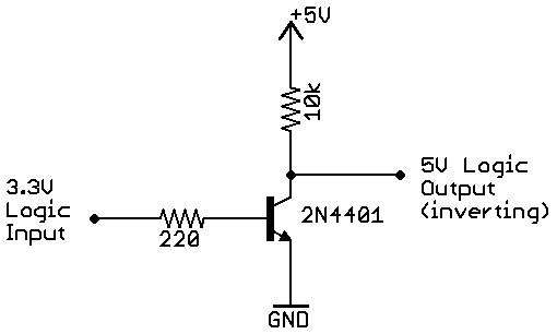
I'd prefer just a simple common-emitter configuration. This circuit inverts the signal, but this could be compensated for in the firmware. If the 5V MCU has pull-up resistors then the 10k could be eliminated.