Have been trying to learn the problem with three inputs at once. Beyond the programming, there is an electrical problem I must be creating.
So I want to use three sonic sensors that take care of the open and closed situation all by themselves. When something is in front of them the circuit closes until that something moves away and then it opens. No big deal. One input is no problem for me and arduino. Two also worked fine. Well not exactly fine, there were some floating issues. I have read all about buttons but have not tried the special libraries yet. Have been really having trouble with three inputs. I finally got it working totally clean using a breadboard and DPDT switches in place of the sensors. Problem is that they only work with the switches in a particular order and I don't know why. I am putting up a picture of the breadboard swithch setup that only works in a particular order when it goes into the arduino. I have checked that 4.5+v is flowing when the switch is in the on position on all three at once. Arduino only sees three when they are in a particular order. I have confirmed this with Serial print and Toolduino from Nootropic design. This is the order that works.
What have I done that creates this problem and what can I do to avoid it?
The code would just be the serial print commands with the inputs serial printing whether they are high or low.
Like I said it does it using no code at all when you check the arduino inputs with toolduino.
It is basically a troubleshooting program for arduino boards. Free and very helpful.
If you go to Nootropic design look for toolduino and it will explain what it does and how it does it.
Whoops, that is just a drawing error. It is connected to 5v and ground.
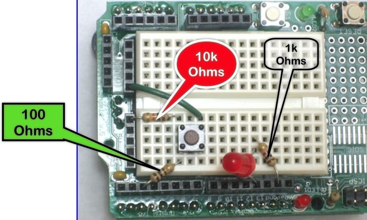
Here is the breadboard corrected with resistor values and a picture from a button tutorial from Adafruit.
Assuming those are SPDT switches, and they sure appear to be, why not just attach one pole of each to +0V and the other to +5V and the common of each to a digital pin on the Arduino. Set the pins as input and poll them. When a switch is set to the +5V pole it should register on the pin as HIGH and when it is set to the +0V pole it should register as LOW. KISS.
Yes, you can attach resistors, but the Arduino isn't going to pull significant power anyway.
What is going on with the Adafruit demo is different. It is a SPST switch that is being pulled up to +5V through a 10k resistor when the switch is open and is draining that +5V to ground (thus is looks like +0V to the Arduino) when the switch is closed. SPDT is easier to implement, you don't need to pull up or pull down although there may be a middle position on the switch that will connect neither pole to the Arduino and in that position the pin will float and might give either value. But for this, a simple project, I would just connect it as I said, that is how I started out.
One last edit. If you don't have this, you certainly should buy one:
This will tell you if a pin or wire or whatever is set high or low or has no signal. I bet if you checked the Arduino pins and connections along your circuit with a logic probe the circuit / Arduino pins would not be doing what you think they are doing and it would be a huge hint to let you know exactly what is wrong. I suck at soldering. Whenever I solder something I go over it with a logic probe before I start plugging expensive parts into my sockets.
Assuming those are SPDT switches, and they sure appear to be, why not just attach one pole of each to +0V and the other to +5V and the common of each to a digital pin on the Arduino.
Because if they are not a break before make type you short out your power supply every time you change it over.
Thanks for the replies. In answer to your switch connection, I am using something to simulate the closing of a relay. The two wires from the switch are the same as N.O. contacts of a relay (attached to a sensor). When the relay closes it is like me moving the switch to connect both wires like the relay would.
The 4.5+v is definitely getting to the arduino. They all work individually but the arduino is not recognizing them unless they are is a particular order.
Stated another way, the arduino input pins don't change they are always 4, 5, and 11. If switch 1 and 2 (left to right) are in 4, and 5, then 5 doesn't go high. If switch 1 goes to 4, switch 2 goes to 11, and switch 3 goes to 5 they all go high when all the switches are closed.
So if the switches are next to each other on the breadboard they can't be next to each other in the arduino or one of the pins won't go high. This is why I thought there was some rule broken. Something rule that would lead to the switches being better isolated from each other.
The logic probe looks like a good tool to have around, thanks for the suggestion.
Toolduino gets the same job done but needs a computer. To use it you run the StandardFirmata sketch then startup Toolduino. It then gives you a graphic representation of the arduino and what is happening to all of the pins. Toolduino also shows that all three pins are not going high unless the pins have a particular switch in them. This is how I figured out that there was a way to get all three to work at the same time.
Assuming those are SPDT switches, and they sure appear to be, why not just attach one pole of each to +0V and the other to +5V and the common of each to a digital pin on the Arduino.
Because if they are not a break before make type you short out your power supply every time you change it over.
Thank you for that bit of insight. Is there any way to know if a SPDT switch is break before make or make before break?
The ones that I have used in my little breadboard projects are these:
Is there any way to know if a SPDT switch is break before make or make before break?
It will say it in the data sheet. Mind you that Amazon link has no data sheet associated with it so you would have to track down the manufacturers site or ask them the question.
Sorry I am having such a problem making my situation clear. Have tried to explain to the best of my ability. My code works fine. This is the General Electronics section and I am only asking a question about the electronics. In the very beginning I stated that I am using sonic sensors with Normally Open relays in them. Since the drawing program used doesn't include sonic sensors I used those switches. This part seems to have been missed or I screwed up my description in another way.
I am using three relays as the switches. These relays do not include arduinos in any way. The switches shown in the picture are representations of the relays. Didn't know what else to use and didn't think it mattered that much as long as the message said they were relays.
Anyway seems the pictures have disappeared. I will repost the one that counts with a slight redraw.
We are asking about your CODE because it is your CODE that processes the INPUTS that you state you are having a problem with. Is that clear enough?
We do not sit around and ask people for information because we are bored. You came to US for help, feel free to ignore our requests for further information and solve this problem YOURSELF.
So you want to have the 3 relays (closed by sensors) detected as either all open, or 1 or more closed?
Wire the 3 sets of contacts in parallel with one end grounded and the other end going to an arduino pin with internal pullup enabled.
If all are open the pin reads as high, life goes on.
If any one closes, the pin reads as low, life stops until the pin reads high again.
Just a thought: I have no idea what sonic relays are, but if they're emitting and detecting sound to close a switch (like a ping sensor), maybe they're interfering with each other? That would explain why one works fine, two get a little flaky, and three don't work at all.