Hello.
Was wondering if someone can explain how a ultra sonic senor works. Am I right in that it has two parts an emitter and a receiver. Would it be possible to split these two parts into seperate componets
Hello.
Was wondering if someone can explain how a ultra sonic senor works. Am I right in that it has two parts an emitter and a receiver. Would it be possible to split these two parts into seperate componets
Hey,
thats's pretty easy:
the emitter sends an ultrasonic sound which bounces off of objects in front of the sensor.
The receiver's receiving the bounced-off signal and then the sensor is calculating how much time went by. (in a microsecond-range)
Then the microcontroller divides the time by the speed of sound (1,126 ft per second) and gives you the distance!
When emitters and sensors are combined in a system they are often referred to as "transducer"s.
Yes, you certainly can separate them ... especially when you want to isolate the characteristics of the transmitting element from the receiving element ... for the same reasons we don't (usually!) use loudspeakers for microphones, or LEDs for photosensors.
Piezo crystals are unique in that some of them can be used for BOTH functions, and some of them are really inexpensive, so they get used a lot when it's ok for the echo to bounce back to the emitter's location. Bats use one emitter and two sensors ... when the echo arrives back at one ear before the other, they get a sense of direction in addition to distance.
Its possible to use a single transducer for transmit and receive - but this requires a transmit/receive changeover circuit to allow the transducer to both transmit high voltage signals and be connected to a sensitive receive amplifier. Vehicle reversing/parking sensors typically are like this.
Using a separate transducer for receive and transmit means the transmitter can be optimized for high power output and the receiver optimized for sensitivity, as well as isolating the receiver from transmitter and making the circuitry simpler (no transmit/receive signal switching).
MarkT:
Its possible to use a single transducer for transmit and receive - but this requires a transmit/receive changeover circuit to allow the transducer to both transmit high voltage signals and be connected to a sensitive receive amplifier. Vehicle reversing/parking sensors typically are like this.Using a separate transducer for receive and transmit means the transmitter can be optimized for high power output and the receiver optimized for sensitivity, as well as isolating the receiver from transmitter and making the circuitry simpler (no transmit/receive signal switching).
Actually a "switchover" system isn't typically used; this is difficult to describe, but basically everything is connected together (the output and the input), and "buffered" via a couple of back-to-back diodes (reverse polarity to each-other in parallel - hard to describe, and looks even weirder in schematic form) to the receive amplifier. So - what happens when you ping is the receiver gets a "spike", but the diodes protect against this spike; since the system knows that it has sent the spike, it waits to "listen" for the echo after the spike. The main downside of this system is the fact that there is a "settle" time after the ping, so if an object gets very close to the sensor, the distance become immeasurable because it is in the "wait period", or is swamped by any lingering "settlement" noise.
On my other computer I had a link to this kind of circuit which was detailed on a ultrasonic transducer manufacturer's site; if I can dig it up later I will post it here (that, or you can look it up on one of my other older posts - I know I have posted about this before).
![]()
I call that diode switching! The cheap parking sensor units have transformers to boost output voltages to 40V or so and I suspect (been a while since I looked at it) they use a large value resistor and diodes to protect the input circuit, and have more circuitry to switch between 4 different transducers (all with own tuned transformer)... I think the transmit pulse was actually 4 cycles at 40kHz...
Thank you all very much brilliant info, loved the bat description.
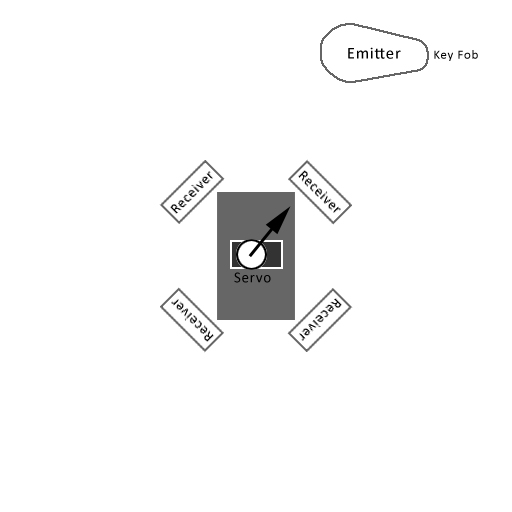
What I was looking to do, was have a base with 4 or 3 receivers and a separate fob with an emitter. Then by which receiver gets the strongest signal will give the base station directional info to rotate a servo. Will this work?
I've attached a image layout.
cheers
MarkT:
I call that diode switching! The cheap parking sensor units have transformers to boost output voltages to 40V or so and I suspect (been a while since I looked at it) they use a large value resistor and diodes to protect the input circuit, and have more circuitry to switch between 4 different transducers (all with own tuned transformer)... I think the transmit pulse was actually 4 cycles at 40kHz...
See the example circuits here:
As was explained to me on another forum, the purpose of the two diodes "...is to clamp the TX pulse signal at the receiver amplifier input to 0.7V, for the low level echo RX signal the diodes appear as an open circuit..."
To me this isn't "switching" - but rather "buffering" or "protection". It would be interesting, though, to see a schematic for the parking sensors you are talking about; it sounds like its doing something similar - though switching between multiple transducers (I was only talking about a single transducer used both as a transmitter and receiver, vs the seemingly more common and inexpensive method of separate transducers used on products like the Parallax Ping and similar).
![]()