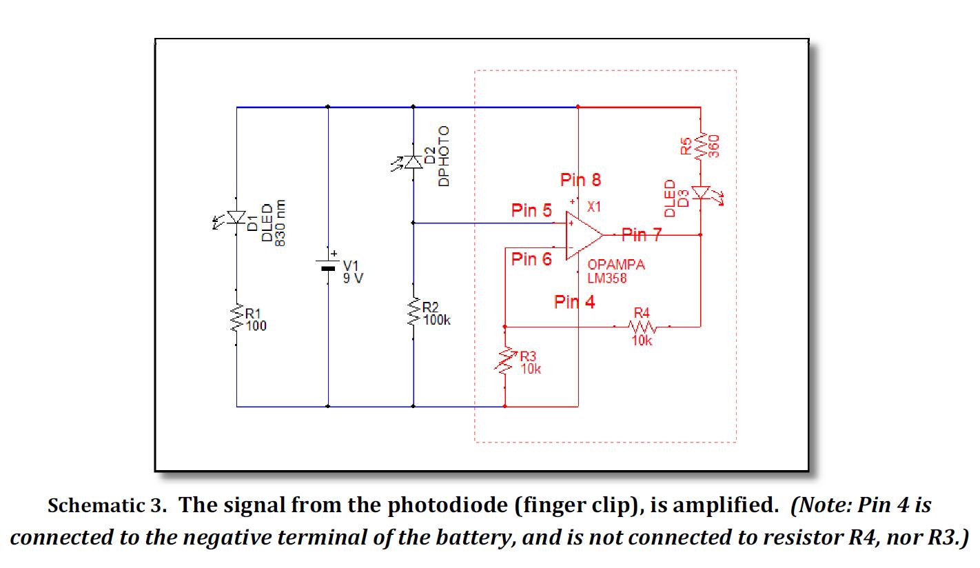
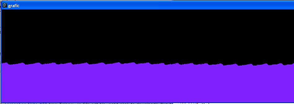
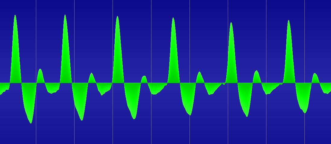
I am trying to make a heart rate detector using infrared light emitter/detector placed on a finger clip, using the schematic in schematic.jpg. Actually, I use an LM324 instead of LM358, that's what I found around the house. When connecting the Vout pin of the amplifier to one analog input of the Arduino (and, of course, the finger being between the infrared emitter and the receiver), I get the signal in Arduino.jpg. Preety nice, but when I connect the same Vout pin of the amplifier to the soundcard microphone input of my computer, I get the smooth and much more nicer signal you can see in soundcard.jpg. I mean, the variation of the pulse wave is all around zero line, no matter how it varies. Is there a way I can accomplish that with Arduino, I mean filter out the DC from the signal so only the pulse wave to remain? It's like the soundcard has some filters in int that I cannot emulate with the Arduino. I tried placing a 100nF capacitor in any imaginable way, but no result. The DC under my pulse wave is still there.
I want to do this because it is easier to apply a threshold to the sinal to calculate heart rate. Is there another way to identify each individual heartbeat in my signal?. Keep in mind that the ups and downs of the pulsewave are not always around a constant (like 0 in the case of the soundcard). It depends, for example, of how much ambiental light there is in the room. If somebody comes into the room and turnes on the light, the pulse wave remains (my heart is still beating), but the DC below the signal is different.
the analog inputs on the arduino only like positive voltages (between 0 volt and 5 Volt / Analog Reference Voltage), see http://www.arduino.cc/en/Reference/AnalogRead.
Filtering out DC will not solve your problem.
It does seem like your amplitude is quite low.
Probably your soundcard is more sensitive.
Although I'm definitely not an electronics expert, I would suggest at the very least checking the average output voltage.
That should be approximately 2.5Volts, giving you a nice average of 512 when using analogRead.
If it is below, you can set the analog reference voltage to something more usefull (your peak voltage), see analogReference() - Arduino Reference for more info.
You could also try to give the signal the proper DC offset and amplitude, but that would require electronics knowledge which I don't have...
If you want to "filter" dc in software, that's also possible.
I used something similair to the code below to deal with a varying offset (not the actual code, and not tested, but this should work without much changes).
What this does is sample the last 4 readings, and check if the current reading deviates from this average by a certain threshold.
The code could also be used with more samples (up to 32 without changing all the integers to longs / unsigned ints).
For me that worked fine, but it depends a lot on the amplitude of your signal.
Hope this helps...
Regards Dennis
const int analogPin = 9;
const int analogThreshold = 40;
bool analogTriggered = false;

void setup() {
  pinMode(analogPin, INPUT);
}

void loop () {
  analogWorker();
  if (analogTriggered) {
    // Trigger code
  }
}

void analogWorker() {
  static int analogAvg = 512;
  static int analogValues[] = { 512, 512, 512, 512 };  // Average last 4 values
  static int analogCounter = 0;
  static int analogTotal = 2048;  // Fill with total of analogValues[] (4x512)
  static int readOut;

  readOut = analogRead(analogPin);
  analogTotal -= analogValues[analogCounter];
  analogValues[analogCounter] = readOut;
  analogTotal += readOut;
  analogAvg = analogTotal >> 2;  // Fast division by 4
  analogTriggered =
    ((readOut>analogAvg+analogThreshold) ||
     (readOut<analogAvg-analogThreshold));
  analogCounter = (analogCounter+1) % 4;  // Cycle through values
}
Meanwhile, I found this. Open Hardware – World Famous Electronics llc.. It is basically the same problem. They transformed an unusable signal in a signal which could be interpreted as heartrate by using a threshold. They won't say how they did it, but they said they used op a,ps and filters (preety misterious).
Do you have any idea what amp and filter could I use?
However, if you look at the page you found yourself more carefully, you will see that everything is already in the schematic.
Apparently they use a "MCP6001" op amp as stated in the right of the schematic.
The filtering seems to be a worked out version of a simple low-pass filter.
(See Low-pass filter - Wikipedia for details about this.)