i want to read the temps from my central heating system.
I don't have the specs of the thermistor's but tables from the central heating manual (see attachment).
I can measure the voltages with my multimeter and if i look into the tables it looks ok.
But all thermistor reading examples i find require the usage of the Arduino voltage (voltage divider circuit).
Is there a way to read the voltages from the thermistors without coupling the central heating and Arduino voltage?
Attachment:
Table 1: furnace water temp & underfloor heating water temp
Table 2: outside air temp
Table 3: hot water storage tank (water temp)
First, check that there a common ground connection for all 3 thermistors. If there is, you can use 1 sensor board to measure 3 voltages with respect to that ground, all with the range 0 to +5v. You can make that sensor board using an ADUM6401 digital isolator http://www.analog.com/static/imported-files/data_sheets/ADuM6400_6401_6402_6403_6404.pdf and a 4-channel SPI ADC chip such as http://ww1.microchip.com/downloads/en/DeviceDoc/21298e.pdf. Conveniently, you can buy an evaluation board for the ADUM6401, which saves you making a PCB yourself. You can wire the ADC on the prototyping area of the board.
Not only does the ADUM provide isolation between the ADC and the Arduino, it also provides a 3.3V or 5V isolated power supply to the ADC. Note that there is a minimum load that you must put on the isolated power supply. I normally provide this load using an LED and series resistor, so that I can see that there is power on the isolated side.
A lower cost alternative would be to use opto isolators to isolate the ADC from the Arduino, but then you would still have to provide power to the ADC chip somehow.
Yes all thermistors have common ground.
I have 4 so i need 2 ADUM6401.
The central heating connections are:
AF1 = 0 volt ground
AF2 = outside air thermistor
KF2 = furnace thermistor
VF2 = underfloor heating water thermistor
BF2 = hot water storage tank thermistor
The ADC chip means i read the voltage on the Arduinos digital inputs?
Do you have an example circuit diagram to give me a kick-start?
MrGlasspoole:
Ah, didn't know this dc-dc-converters.
Yes all thermistors have common ground.
I have 4 so i need 2 ADUM6401.
No you don't, you just need a 4-channel ADC (such as the MCP3204 that I suggested) and one ADUM6401.
MrGlasspoole:
The central heating connections are:
AF1 = 0 volt ground
AF2 = outside air thermistor
KF2 = furnace thermistor
VF2 = underfloor heating water thermistor
BF2 = hot water storage tank thermistor
Good, you have a common ground connection.
MrGlasspoole:
The ADC chip means i read the voltage on the Arduinos digital inputs?
Do you have an example circuit diagram to give me a kick-start?
I don't have a circuit diagram that I can share, but here is an outline. Connect the MOSI and SCLK pins of the Arduino and one other digital output to the 3 inputs of the ADUM6401. Connect the ADUM6401 output to Arduino MISO. On the isolated side, connect the three ADUM outputs to Din, CLK and CS respectively of the MCP3204. Connect MCP3204 Dout to the input on the isolated side of the ADUM. You will also need a smoothing capacitor on the ADUM power output, and an LC network to feed the Vref pin of the MCP3204.
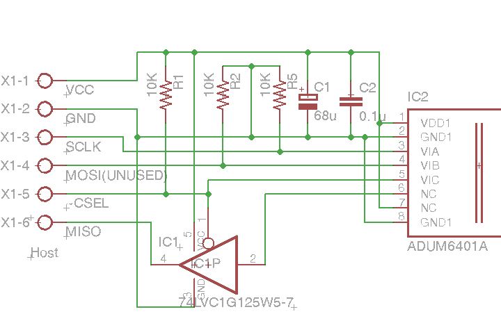
Yes, you do need smoothing capacitors, see the ADUM6401 datasheet for the recommendations. I attach a schematic of the arrangement I have used when I need a 3.3V output. For 5V output you need to connect pin 10 to VDD2 instead of GND2, also increase the LED series resistor. The LED provides the recommended minimum load of 10mA. C6 is the decoupling capacitor for the MCP3204 and MAX6145.
EDIT: also you need to connect pin 12 (AGND) of the MCP3204 to the isolated supply ground side.
You may get away without the LC network, it's hard to say without trying it, it depends on how sensitive the MCP3204 is to power supply noise, and how precise and stable you need the voltage readings to be.
The MAX6145 should take is input from the filtered supply.
Pin 14 of the MCP3204 should go to the filtered supply (+ve side of C2), not the unfiltered supply
C2 in my design was 22uF, not 220uF
You also need 10uF or 22uF in parallel with 100nF between pins 16 and 9 of the ADUM6401 (the evaluation board is laid out for 22uF and already has the 100nF)
Pin 12 of IC1 should be connected to pin 7, and separately connected to the common side of the voltages to be measured
If you use the evaluation board, it is laid out for a 68uF capacitor at C5, and C4 is already on the board.
I suggest you include 10K resistors in series with the MCP3204 analog inputs, to give some protection against voltage transients
The 3 channels passing signals to the isolated side of the ADUM6401 are interchangeable.
You have a choice of how you interface the Arduino Mega to the device:
For maximum speed, use hardware SPI. In this case, the SCLK pin of the Mega must be routed to SCK of the MCP3204, MOSI must be routed to Din, and Dout must be routed to MISO. You can route any other output pin on the mega to CS on the MCP3204. Maximum SPI speed is 1MHz if you use the A version of the ADUM6401, and as high as the Mega will go (8MHz) if you use the C version. However, if you want to share the SPI subsystem with other devices, then you need to connect a tri-state gate between the ADUM6401 channel D output and MISO (I use a 74LV1G125 for this - it is an SMD device).
Alternatively, use any 4 pins you like on the Mega and use software SPI. The achievable data rate will be lower, although you can probably approach 1MHz if you use direct port access.
Ok, i now first order parts that i can start to build something.
But i can't find the 74LV1G125. Not at farnell, not at digikey and in no German shop...
I think it's more future prove to use the 74LV1G125 cause i want to log the data to a SD card
have the network shield and also want to build some radio control for a water-pump (enocean if possible).
Does the wire from the heating system thermistors to the MCP3204 not affect the output of the thermistors (wire resistance)?
Or the 10K resistors? Not that the heating system turns into a air conditioning systems XD
Maybe its a big thing for an Arduino beginner. But like cabinetmakers say: "start with something
you like and something you have fun with. Don't select your project by easy or difficult".
I think it's learning by doing. And if the help here is so great like yours, than we can build a machine
to take over the world *lol
Put 74LVC1G125W5-7 into the Farnell search box, that's the exact part number and it finds it. I attach a schematic of how I connect it. I use a 6-pin SOT23 breakout board from Sparkfun or Futurelec, which I solder on to the eval board using a 2-pin header. Or you could wire it dead-big style. The 10K pullup resistors in the schematic keep the signals clean while the Arduino is powering up.
The MCP3204 has a very high input resistance, so it doesn't affect the voltage you read from the thermistors, neither do the 10K resistors affect it. If there is any noise on the signals being measured, the you might want to put a capacitor (e.g. 1uF ceramic) between each of the analog input pins and AGND, so that it and the 10K resistor act as a low-pass filter.
Now i need to read allot about the SPI stuff and why it's now hardware with the 74LVC1G125W5.
It means i need a 74LVC1G125W5 for every device now that uses SPI (SDcard, Ethernet...)?
MrGlasspoole:
It means i need a 74LVC1G125W5 for every device now that uses SPI (SDcard, Ethernet...)?
No, devices that use true SPI protocol always have 3-state outputs on the data out pin. But the ADUM6401 is a generic device not specifically intended for SPI, and unfortunately it doesn't have 3-state outputs.
You have the output of the MAX6145 shorted to ground.
Pin 1 of IC2 needs to be driven low by the same signal that drives the CS input of ADC low. You are using Voa to drive CS low. So you need to connect pin 1 of IC2 to Via of the ADUM6401, not to Vic. Alternatively, swap the ADUM6401 channels around.
I thought the Arduino SCK (D52) must be routed to SCK of the MCP3204?
If i swap them "Arduinos SCK" goes to "CS of MCP3204" and "CLK of MCP3204" to a digital pin of the Arduino?
MrGlasspoole:
I thought the Arduino SCK (D52) must be routed to SCK of the MCP3204?
If i swap them "Arduinos SCK" goes to "CS of MCP3204" and "CLK of MCP3204" to a digital pin of the Arduino?
Correct; so if you swap the ADUM6401 inputs around, you must swap the outputs in a similar way. However, pin 1 of the 74LV125 must be controlled by the same signal that controls CS on the ADC.
I just want to let you know that i already have some parts but not all and
that i also need to figure out some other stuff.
I will build it - not that you think your efforts on teaching me this was to no avail