L298 H-bridge motor controller

Hi all,

I seem to have found lots of questions about this topic, around various forums, but no answers that have helped me get things working.

I'm trying to drive a simple DC motor by using a L298 H-bridge (http://www.st.com/stonline/products/literature/ds/1773/l298.pdf) and my Arduino.

I've been following the schematics here, which seem to make sense to me:
http://www.pyroelectro.com/tutorials/l298_control/schematic.html

Yet both my output pins, that go to the motor, always seem to display the same voltage, which is whatever is coming in as my power supply voltage. This is the same whether I hook up 2 AA batteries to the power supply or try to use Vcc from the Arduino.

Any ideas what I might be doing wrong?

Many thanks,
Josh

Hey

sounds like a power supply problem.

The L298 needs two supplies: 5V for logic (take from arduino) and something higher for the motor supply.

The specs say that the motor supply needs to be at least 5V or so; 3V from 2xAA batteries is not going to do it. Try connecting 9V or 12V as the motor supply, and double check your wiring too. Avoid using the Arduino 5V supply as motor power, as it can bring noise back to the Arduino, and it's also not rated for much current.

Hmmm, thanks for your help.

I've since tried a 9V rechargeable RC-car battery, and still seeing the same behavior.

I've double, and triple checked the wiring, and even tried two different L298 chips, in case of a bad chip.

I'm still confused :frowning: Any further advice, or simple suggestions on how to wire this thing up to make sure my H-bridge is functioning properly will be greatly appreciated.

Thanks!
Josh

Are you actually providing the proper control signals to the driver?

Are you actually providing the proper control signals to the driver?

That there, is a very good question :-/
I thought it was as simple as providing HIGH to one of the inputs and LOW to the other, but I seem to be beginning to understand that's not the case?

Are you pulling up the enable pin (or setting it HIGH through either digitalWrite/analogWrite if the enable pin on the H-bridge is connected to your arduino)? Unless the enable pin is HIGH there is no current flowing to your output pins.

Also maybe having a common ground between your motor supply and the arduino supply.

That's all I can think of.

Are you pulling up the enable pin (or setting it HIGH through either digitalWrite/analogWrite if the enable pin on the H-bridge is connected to your arduino)? Unless the enable pin is HIGH there is no current flowing to your output pins.

Yup :frowning: Enable pin is set to high, reading 4.8V

Also maybe having a common ground between your motor supply and the arduino supply.

Tried it :frowning:

Thanks for the help guys... I'll keep poking at this and I'm sure I'll eventually figure it out. :cry:

What happens if you disconnect the 298? Are then your output pins acting as expected? Did you set them as outputs on setup?

I do agree it should be quite straightforward circuit.

Sorry if this is too much of an insult but have you connected all the earths on the unit together. These are the points marked with that triangular type symbol and should all be connected to the 0v line. I say this because my students often didn't understand that was what the symbols meant.

Another consideration is that sometimes motor drivers require a load in order to function properly. Can you try taking the measurements with a load such as a resistor (or a motor, but this might make the readings slightly noisier) across the driver outputs? By the way, make sure you choose a resistor or motor that won't demand more current than the driver can safely deliver.

  • Ben

hi

i've been digging around the forums looking for that puzzling connection between the L298 and arduino, and thought best to pull up an old post rather than start a new one.

i'm using another L298 based driver kit to (hopefully) drive a 12V 2A motor. i know i've made the kit up correctly but haven't yet been able to get the motor to respond.

so far i have:
12V going to the voltage in on the board
pin 2 on the arduino going to en on the board
pin 9 PWM on the arduino going to IP1 on the board
ground from the 12V supply tied to ground on the arduino

i'm doing my testing using maxuino and max/msp and have set pin 2 to high and have tried using both a digital high and PWM from pin 9 - so far without luck.

can anyone point out to me the mistake i'm making or the thing i'm missing out?

cheers

Just for giggles, try this:

Wiring:
Arduino L298
digital pin A -> Input 3
digital pin B -> Input 4
PWM P -> Enable B

Sketch:
setup() {
pinMode(A, OUTPUT);
pinMode(B, OUTPUT);
}

loop() {
digitalWrite(A, HIGH);
digitalWrite(B, LOW);
analogWrite(P, 128);
delay (500);
}

You can choose A, B, and C, but they must be different, and C must be a PWM pin.

This is the simplest way to debug these type of things that I've found.
As long as the two Input's are different, something should happen.

HTH
GB

WARNING - this code is unVerify'ed and untested

Looked at the datasheet for the L298D, and they recommend
RS1 = RS2 = 0.5 [ch937]
for the sense resistors.

They explicitly say

1.1. POWER OUTPUT STAGE
The L298 integrates two power output stages (A ; B).
The power output stage is a bridge configuration and its outputs can drive an inductive load in common or differenzial mode, depending on the state of the inputs. The current that flows through the load comes out from the bridge at the sense output : an external resistor (RSA ; RSB.) allows to detect the intensity of this current.

This may be a problem too. What value resistor (if any) is connecting 'Sense' to ground?

HTH
GB

hhhmmm... sense resistors. i'm not using any...

this is the driver board - bloat.me. it has motor power in, power out for two motors, IP x 2 and EN for each motor and regulated 5V out. is it this 5V out which i need to connect back to the ground? doesn't seem to make much sense.

here's a schematic for the board too

From my reading of the datasheet, I don't believe it needs sense resistors. But if if they're there, they need to be low enough to conduct all the current through the load (motor) to ground without dropping too much voltage (or constraining current).

The L298 DC Motor Control - Schematic | PyroElectro - News, Projects & Tutorials link has a 10 ohm resistor in that ground path.
I was raising the sense resistor to folks attention because it likely makes matters worse, or more confusing.

HTH
GB

looking at the schematic and the board itself it appears that the sense pins of the L298 are already connected to ground...

blamski, I agree that your schematic has no sense resistors in the grounf path.

But the OP referenced L298 DC Motor Control - Schematic | PyroElectro - News, Projects & Tutorials as the schematic that they were following, and it has 10 ohm resistors in the Current Sensing B path to ground. Looking at the datasheet that connection is the from the 'bottom' of the H-Bridge to ground.

The L298 DC Motor Control - Schematic | PyroElectro - News, Projects & Tutorials schematic has got a connection from the pin marked GND to ground, but, looking at the datasheet, that GND pin is not the H-bridge ground. It is very probably the 'logic' ground.

HTH
GB

Blamski, Try hooking the other input pin to ground. It might not work if the pin is simply not connected.

The current sensing resistor is in series with the load--the bridge ground is separate than the chip ground, as stated. If the resistor is too big, a motor won't run--I found this the hard way, using pyroelectro's suggested setup. My .6 amp motors weren't running on 9V with 10 ohms, a potentiometer indicated that the max for the current sensing resistors is 4-5 ohms for my motors. :wink:

Technically, you don't need the resistors if you're not trying to limit the current. Running them straight to the breadboard's ground bus seems to work for me. There's a few situations where a resistor makes sense, but I can't see most setups needing it.

If you feel you need a sensing resistor, then you need to put a potentiometer in to start, and find out where the cut-off is, and what value works best. Then you need to make sure the resistor is rated properly--most people will use a 1/4 watt since that's the most common, but my motors for example pull over 5 watts, and so I'd need a much larger resistor to run it properly.

Technically, you don't need the resistors if you're not trying to limit the current.

These resistors are not intended to limit current.

If you feel you need a sensing resistor, then you need to put a potentiometer in to start, and find out where the cut-off is, and what value works best.

Don't do this. As explained in the datasheet. It is not there to limit current, it is there to allow measurement of current.

[edit]Unless it is a low resistance 'power' potentiometer designed to dissipate heat, it would be lucky to get close to a reasonable value before getting damaged.

Low value power potentiometers are often wire wound, with significant inductance, which will likely react with the motor, so the DC resistance value measured with an ohmeter will probably be misleading.

If the motor uses such a small amount of power that an ordinary potentiometer is okay, then the motor used so little power that the L298 would be very unlikely to be damaged by the motor.[/edit]

The purpose of the sense resistors is so that an external system can detect how much current is flowing through each motor (load).

By measuring the voltage drop across a fixed resistor (the sense resistor), the current flowing through the motor can be deduced from Ohm's Law:
I = V / R

Put a low value resistor in the path from the sense resistor pin to ground (say 0.1 ohm, to make the arithmetic easy, with a power dissipation, of say 1W), and
Measure the voltage dropped across the sense resistor using an analogue input on the Arduino
I = V * 10 (for an R of 0.1, and remembering that 1V is approx 100)

This allows the Arduino to be used to monitor the current through the motor, and even decide if it is stalled, and switch it off.

HTH
GB
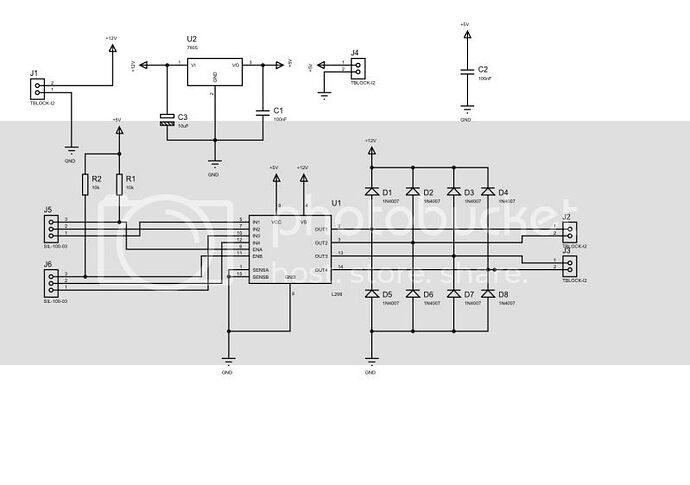
The data sheet says to use filter diodes to protect the motor controller from back EMF from a motor. Would a similar setup between a wire wound resistor and the motor do the same, or just be a pointless exercise?