Hello All,
I have been interested in electronics for years but never quite become proficient.
My interest has been rekindled by the discovery of the Arduino system.
I have ordered the Uno R3 and while I am still waiting for it I have a simple question:
Once I am done with the first sketch (say, something fancy like blinking an LED) can I unplug the ATmega from the Arduino board and put it on a standalone breadboard (with the addition of the needed LED, resistor(s) power supply ecc.) and have the LED blink away happily, while I plug a NEW ATmega on the Arduino board and work on my next great project (say, blink TWO LEDs)?
Yes.
Need 16 MHz xtal, two 22pf caps, 10K reset pullup resistor, 3 0.1uF (100nF) caps, and 3 AA batteries for power.
All can be obtained from www.dipmicro.com pretty inexpensively with low shipping costs.
Maybe this kit with a couple of extra bits will do you nice.
Is the second part of my question also true?
I.e. can I just buy a bunch of ATmegas and plug them (one at a time of course) into the Arduino board for my next projects?
Yep. That's sort of the idea. To be "an Arduino" (as opposed to "an AVR"), you need the Arduino bootloader programmed onto the blank chips. This is possible via the "Arduino as ISP" sketch, which deflowers the virgin chips. All it takes is one pre-made board to clone an army of DIYs.
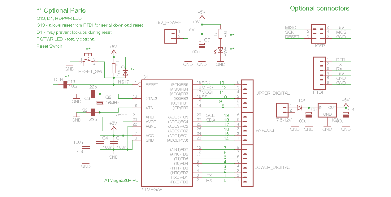
Here's pretty much the bare minimum you need:
ATMega328P-PU or -PN
16 MHz Xtal
two 22pF caps
three 0.1uF caps (100nF)
10K resistor
connectorize as your needs demand.
You can even eliminate the crystal and 22pC caps too. There is a bootloader that works without them, but the chips runs at half speed. If you do not need the full 16mHz, you can save a bit of money and construction time.
I also ordered the kit from dipmicro as suggested.
After "talking" to you I found this tutorial, that details what you have been explaining:
What bothers me is that it says: "Note that these techniques only work with the Arduino Duemilanove w/ an ATmega328, not the Arduino Uno (or older Arduino boards w/ an ATmega168)."
Now, the one I just ordered is precisely an Arduino Uno R3, but it has an ATmega328P.
The Note comes just before the paragraph: "Burning the Bootloader" but after that you find the paragraph "Uploading Using an Arduino Board".
In the latter, they instruct you to remove the Microprocessor from the Arduino board and in both cases 'To program the microcontroller, select "Arduino Duemilanove or Nano w/ ATmega328" '.
So, the exclusion of the Uno appears to refer to both situations.
Put your new part on a solderless breadboard, with 16 MHz xtal, 22 pf caps, 10K reset pullup resistor.
Connect Uno's +5 to VCC/AVCC pns, Gnd to Gnd, D13 to D13, D12 to D12, D11 to D11, Uno's D10 to blank chip's reset.
Or make these connections to your standalone board if there is no conflict on the pins.
Put newly bootloaded part in your Uno and download a sketch, or download on your new hardware if it supports that, maybe using an FTDI Basic or CP2102 USB/Serial adapter if not.
You should take a look at Breadboard Arduino Compatible Parts Kit Retail - RTL-10422 - SparkFun Electronics for how to build a breadboard arduino. Look at the links halfway down the page for directions for assembly. There is also a printable overlay to put on your breadboard to make assembly very easy. You don't have to order the kit, use your own components if you have them.
I use this to make a "sacrificial" arduino for testing where the unit may be damaged or lost. Worst case, I'm out $12, but I have a fully functional and programmable arduino.
In addition to what CrossRoads mentioned, you'll need an FTDI breakout or cable for programming. I tried the remove/program/reinstall route. It isn't convenient and you end up breaking chip leads. Buy the FTDI programmer and make the breadboard programmable. The FTDI is $15 or $10 if you buy the female adapter separate and solder it on (SparkFun FTDI Basic Breakout - 3.3V - DEV-09873 - SparkFun Electronics and FTDI Basic Breakout - 3.3V - DEV-10009 - SparkFun Electronics). You'll also need a few inches of 26 gauge hookup wire or use your breadboard jumpers if they aren't too long.
Trying to build a scoreboard, with some 7-segment displays that will be on separate circuits, and this is what I plan on using for a circuit
I'll have a 16 MHz crystal between pins 9 and 10, then caps connecting to ground.
Pins 7 (VCC) and 20 (VCCA) are connected to 5 volts, then 2 caps then to ground
Pin 21 (AREF) is connected to a cap, then to ground.
Does this sound about right?
**** All the resistors connected to the ULNs and the two at the bottom are to give me places to hook up the oversized 7-segment displays on the PCB. Some of the extra resistors hooked up to the analog pins are going to be switches as well. Again, just to give me some holes to solder wires into for the PCB.
Looks pretty good.
Do not connect CD+ on the ULN2003s to anything, that pin is only used when motors are being driven.
I personally would leave D0/D1 free for serial comms/sketch downloading, especially as you have other pins free.
Then add a 6-pin header for a Serial download cable such as an FTDI USB/Serial cable or adapter such as FTDI Basic: Gnd, Gnd, Vcc, Tx, Rx, DTR (DTR to 0.1uF cap, other side of cap to the Reset pin). (might haveTx, Rx swapped, need to check that). Or for a CP2102 USB/Serial adapter.
A0-A5 can be used as D14-D19, with internal pullup resistors, so a switch connecting the pin to ground can be read as button press.
Use a symbol like "MA06-1" for six 0.1" spaced holes good for 0.025" square posts.
Other hole quantities and arrangements are also available, such as "MA02-3" for 2x3 header for an ICSP connector.
My teacher said to connect CD+ on the ULN's to the +12 I'll be supplying the 7-segs so that when the ATMega goes low, it'll supply them with the +12 they need to work, instead of the +5 supplied by the chip. Is this not how they work?
I tried having A0 - A5 connected to ground like digital inputs, but I was getting really screw results while breadboarding. The switches were closing unreliably, just by tapping or getting close to the actual wires without having to actually press the buttons. Once I put the resistors in, that solved all my problems.
Connecting the COM on the ULN2003 to +12V will not do anything for you.
Connecting +12V to your anodes, then a resistor, then the outputs of the ULN2003 is what you need.
A0-A5 - did you try this? Simple test to see if a pin is grounded with a momentary button, internal pullup resistor holds the pin high.
button0 = 14; // pin A0
button1 = 15; // pin A1
button2 = 16; // pin A2
button3 = 17; // pin A3
button4 = 18; // pin A4
button5 = 19; // pin A5
pin13LED = 13;  // on board LED for testing

void setup(){
pinMode (button0, INPUT);
digitalWrite (button0, HIGH); // turns on internal pullup
pinMode (button1, INPUT);
digitalWrite (button1, HIGH); // turns on internal pullup
pinMode (button2, INPUT);
digitalWrite (button2, HIGH); // turns on internal pullup
pinMode (button3, INPUT);
digitalWrite (button3, HIGH); // turns on internal pullup
pinMode (button4, INPUT);
digitalWrite (button4, HIGH); // turns on internal pullup
pinMode (button5, INPUT);
digitalWrite (button5, HIGH); // turns on internal pullup
pinMode (pin13LED, OUTPUT);
}
void loop(){
if (digitalRead (button0) == LOW){  // button0 switch pressed to connect it to ground?
digitalWrite (pin13LED, HIGH); // turn on the onboard LED for 0.1 second
delay (100);
digitalWrite(pin13LED, LOW);
}
if (digitalRead (button1) == LOW){  // button1 switch pressed to connect it to ground?
digitalWrite (pin13LED, HIGH); // turn on the onboard LED for 0.1 second
delay (100);
digitalWrite(pin13LED, LOW);
}if (digitalRead (button2) == LOW){  // button2 switch pressed to connect it to ground?
digitalWrite (pin13LED, HIGH); // turn on the onboard LED for 0.1 second
delay (100);
digitalWrite(pin13LED, LOW);
}if (digitalRead (button3) == LOW){  // button3 switch pressed to connect it to ground?
digitalWrite (pin13LED, HIGH); // turn on the onboard LED for 0.1 second
delay (100);
digitalWrite(pin13LED, LOW);
}if (digitalRead (button4) == LOW){  // button4 switch pressed to connect it to ground?
digitalWrite (pin13LED, HIGH); // turn on the onboard LED for 0.1 second
delay (100);
digitalWrite(pin13LED, LOW);
}if (digitalRead (button5) == LOW){  // button5 switch pressed to connect it to ground?
digitalWrite (pin13LED, HIGH); // turn on the onboard LED for 0.1 second
delay (100);
digitalWrite(pin13LED, LOW);
}
}
There is no reason for the A0-A5 pins to act screwy when they are defined as digital pins. No resistors are needed.