Power saving in code for extended battery life.

Hi,

Im not sure if this is the right section of the forum to be posting this in, but its the best fit i could find.

I have mad a "pee-light", it turns on a nice red glow in the hallway when i get up to pee in the middle of the night.

It has a:

  • darlington photo transistor hooked up to pin A5
  • "Electronic brick (seeed studios)" PIR hooked up to D11
  • 2x LED's hooked up to D10

It tests for light, if it is dark then it tests for motion, if there is motion then it fades on the LED, if no motion detected for 9 seconds, it fades off LED's.

pretty simple, and i have it working exactly as i want it to, with the downside being battery life. I tried it on a 9vold battery and it only lasted 24-36 hours. ive since done some more testing and found out the following:

  • it draws 22mA (both with the PIR off or on)
  • it draws 47mA when LED's are at full brightness (for 9 seconds)

I have read that there are ways to sleep the arduino, but cant really work it out. it could really be off for hours at a time (while its light) but i can only find ways to sleep for 8 seconds.

please can some one suggest ways to improve battery life!??!

here is my code as it stands now. Im sure it looks horrific to all you, im only just starting and have not programmed before (apart from basic HTML 10 years ago!)
anyone has any suggestions on how to make it more neat or efficient that would be much appreciated too. But my main concern is for battery life.

int lightPin = 5;  // analogue pin for testing ambient light
int lightReading;  // value
int LEDpin = 10;   // Pin for LEDs
int pirPin = 11;   // Pin to read from PIR
int pirVal;        // Returned PIR value
int brightness = 0;    // how bright the LED is
int fadeAmount = 2;    // how many points to fade the LED by
int fadeAmount2 = 4;    // how many points to fade the LED by
int pirOnPin = 4;       // Power to this pin is power to PIR
unsigned long timeon;   // the ms val from millis() when LED is powered on
unsigned long timeoff;  // calculated value time on plus 9 seconds
int lightstate = 0;     // records what state the LED is in

void setup(){
 //Serial.begin(9600);
 pinMode(pirPin, INPUT);
 pinMode(pirOnPin, OUTPUT);
}

void loop(){
  lightReading = analogRead(lightPin);        // read light pin from photo transistor
  //Serial.println(lightReading);
  delay(500);
  if(lightReading > 1000) {                   // if light is greater than 1000, eg dark, turn on PIR and strat reading  
    digitalWrite(pirOnPin, HIGH);
    pirVal = digitalRead(pirPin); 
    //Serial.println(pirVal); 
      if(pirVal == HIGH){
        //digitalWrite(13, HIGH);              // used in testing to determine when the PIR was triggered
        //delay(50);
        //digitalWrite(13, LOW);
        //Serial.println("fade in");
        if(timeoff < millis()){                // check that the time the LEd are to be faded out is less than millis(). this stops the LED fading, going stright to off and fading back on on constantly
          int i=0;
          //digitalWrite(13, HIGH);
            for(i=0; i < 255; i += fadeAmount2){  // fade LED on
              analogWrite(LEDpin, i);    
              delay(50); 
            }
           // Serial.println("full light");
            //analogWrite(LEDpin, 255);
            lightstate = 1;                      // set lighstate to "on", so that lights cant be faded off when they are off already.
          }
          timeon = millis();                     // set the time the LED came on to full power
          timeoff = timeon + 9000;               // set the time the LED will fade off. this will be done each time there is motion detected.

        }
    else{
      if(lightstate == 1){                       // make sure LED is on
          if(timeoff < millis()){                // LED has been on for 9 seconds
            //Serial.println("fade out");
           // digitalWrite(13, LOW);
            int i = 255;
            for(i=255; i > 0; i -= fadeAmount){  // fade off
                analogWrite(LEDpin, i-1);    
                delay(50);  
            } 
          //Serial.println("light off");    
          //analogWrite(LEDpin, 0);
          lightstate = 0;                        // LED state is off
          }
      }
}
//Serial.println(timeon);
//Serial.println(timeoff);
//Serial.println(millis());
}
else {
  digitalWrite(pirOnPin, LOW);                   // ambient light has come back up (morning, or hall way light)turn off PIR
if(lightstate == 1){                             // if the LEDs are on, fade off regardless of 9 seconds 
   //Serial.println("fade out");
   int i = 255;
   for(i=255; i > 0; i -= fadeAmount){
   analogWrite(LEDpin, i-1);    
   delay(50);  
  } 
   //Serial.println("light off");    
   lightstate = 0;                               // reset variables
   timeoff = 0;
}
}
}

Thanks for looking,

Gr0p3r
What you could probably do is put it to sleep on an external interrupt and hook the light sensor up to a digital interrupt pin so that when it goes dark, the pin is triggered and Arduino is awoken from sleep.

Another option would be to sleep it using the watchdog timer, and just have it check the light level every 8 seconds, if it's not at what is should be, go back to sleep.

I'd love to see some example code for putting the unit to sleep using the the watchdog timer and to wake it up every 8 seconds. I saw the enerlib library but it's very poorly documented. I'd love to set the watch dog timer to actually go for 15 minutes but it looks like this isn't possible on the atmega chips. it appears 8 seconds is the longest.

The Nightingale code worked for me.

I've based projects on the nightingale code as well. I really want to dissect the enerlib library and figure it out. the enerlib seams to be a lot cleaner way of doing it.

Question...

If you have it sleep for 15 minutes, are you going to stand in the hallway waiting for it to wake up again and check for movement before you walk by? :slight_smile: It needs to be awake to check its sensors, so sleeping for 8 seconds is about the longest that I imagine would be acceptable anyway.

In somewhat-pseudo-code, here's what I'd do:

while (1) {  // Or just in your loop()
  if (it_is_light_out()) {
    // It's light -- sleep for 5 seconds and test again
    snooze(5);
  } else {
    // It's dark -- check for movement
    while (there_is_movement()) {
      light_leds(10);
      delay(250);  // Avoid possibly triggering optical movement sensor based on LED light
    }
    
    // No movement detected -- sleep for 1 second
    snooze(1);
  }
}

You may think that sleeping for a second or 5 isn't much sleep, but consider that (unless someone is there, moving) it's only going to be awake long enough to poll your sensors, then right back to sleep again. I don't know how long that takes exactly, and it depends on what kind of sensors you're using (purely analog? 1-Wire? i2c?), but let's take a very conservative guess and say 100ms. So, for 1/10th of a second every five seconds (2%), your Arduino is running during the day, and 1/10th of a second (10%) every second during the night, vs. 100% as it stands now. That's assuming 100ms, which is probably waaaaaay beyond how long it'll really take.

Which Arduino board are you using?

Putting the CPU to sleep between activities will save a little power (a few mA), but on many of the official Arduino boards (e.g. Duemilanove, Uno, Mega etc.), onboard features like the power LED and USB interface (powered all the time) are what eat up most of the power. Going to something like a BareBones (USB programming interface is a separate board and only plugged in when needed) will save a lot. Once these big guzzlers are taken care of, battery power savings from sleeping the CPU will be worth your attention :slight_smile: A more efficient voltage regulator would help too.

I am working on a low-power Arduino board called Mosquino (basically done, just a few software tweaks needed here and there) that integrates several 'easy' low-power tricks - no power LED, USB stuff unpowered when cable disconnected, low-leakage regulator, and a realtime clock to get the best use of the CPU deep sleep mode. Together this gets the sleep power consumption down to a few uA.

A handful of other things - I don't know whether or not the PIR module you are using has "smarts" builtin to detect motion (and so might need to be powered all the time to work). If not - if it draws less than about 20mA you may be able to power it directly from an I/O pin, sample it periodically (every second or two) and cut the power to it between measurements. Same for an ambient light sensor - assuming the sun does not rise or set too quickly :wink: you might only have to check this once per few minutes before deciding to use the PIR or not, and sleep in between. You can use one of the libraries using the watchdog timer trick mentioned above (rocketscream's Lightweight Low Power Arduino Library is another). But, if you don't mind Yet Another Chip, an external realtime clock (where you can set an alarm for any time in the future) will let you save more power by turning off the watchdog timer too (about 20uA difference in my tests).

Well, so many good ideas.

i would think that it could check for light and if there is light then sleep for 15 mins. that will be fine, once it is dark then change the sleep time to 5 seconds. then put in a bit to say dont sleep for 5 minutes after motion detected (for the return trip :wink: ).

the watchdog idea would be good too (sleep all day and wake at night)

Arrch:
What you could probably do is put it to sleep on an external interrupt and hook the light sensor up to a digital interrupt pin so that when it goes dark, the pin is triggered and Arduino is awoken from sleep.

, but how would that work with a phototrasistor?? it outputs an analogue value, as far as im aware, how can you use that as a digital trigger? example code?

Drmn4ea:

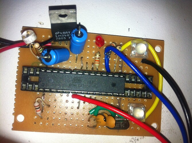
ive made my own board using the atmega. im using an 7805 as a voltage regulator. is that good enough? there is no power led or any other superflous hardware (i think.) i have read about using the internal clock so as to do away with the crystal, that would be something to consider if i could find a nice easy step by step guide where i dont need to buy any extra programmers and dont have the option to brick my chip.

ive attached pictures. the PIR is powered off a digital pin (pirOnPin) and is only activated when a light threshold is reached.
see my code:

  if(lightReading > 1000) {                   // if light is greater than 1000, eg dark, turn on PIR and strat reading  
    digitalWrite(pirOnPin, HIGH);
    pirVal = digitalRead(pirPin);

The LED was only used in testing to notify me when the PIR went HIGH. there is stuff all information about my PIR and the datasheet is useless.
This is it: http://www.robotshop.com/seeedstudio-electronic-brick-pir-motion-sensor-2.html

gr0p3r:
, but how would that work with a phototrasistor?? it outputs an analogue value, as far as im aware, how can you use that as a digital trigger? example code?

An analog value is just a voltage. digitalRead is also reading a voltage, it just "translates" that voltage to either a 0 or a 1. If the voltage at the digital pin gets low enough, digitalRead will start reading it as 0, so you would need to setup a voltage division circuit with the proper resistor values so that it falls below that voltage when you want it to turn on. I think there is a "floating" voltage level (2-3v?) where the digitalRead wouldn't be accurate, so you may have to use an additional device to account for that if the light change is fairly gradual.

i see, do you have a link to an example of the watchdog wakeup trigger? ill have to have a play around and see if i can get that to work. i have a feeling that the light cange is going to be too gradual and it will hit that "floating point" you described and confuse it. what is the device that will switch 0-4v to 0 and 4-5v to 5?

http://interface.khm.de/index.php/lab/experiments/sleep_watchdog_battery/

My first thought would be a zener diode for blocking lower voltages.

Oh awesome, i just googled zenner diode, and going from the pictures, i think i may have some of them already, i didnt know what they were :smiley:

if i can use the nightingale code and get the battery life to 3 years, that would be unbelievable!

anyone know if the 7805 voltage regulator is low-leak like Drmn4ea was suggesting?
also the Nightingale sketch doesnt have a voltage regulator. do i even need one??
will there be an harm in running straight off the battery? i was planning on using a 9v down to 5v through 7805, but if i can run off 4x1.2v AA...
i have found that the PIR i have will give continuous false positives if it is given less than 4v

Some suggestions:

  1. The power consumption of the chip is approximately A * f + B where f is the clock frequency and A and B are constants. At high clock frequencies, the A * f term dominates. So use a much lower clock frequency to save power. Preferably, use the internal 128KHz RC oscillator, which requires programming the fuses. If you don't want to program the fuses, you can still get a substantial power reduction by writing to the clock prescaler register, which allows the clock frequency to be divided by up to 256.

  2. To detect the light level, you can use the analog comparator function of the atmega328p. See the datasheet. This will be more reliable than using a digital input, and gives you two options:

a) Wake up every 8 seconds on the watchdog and read the comparator. This is much quicker than doing an analogRead. So if it is light you can have the processor go back to sleep immediately, having consumed hardly any power.

b) Use the analog comparator interrupt to wake the process up from deep sleep when it gets dark.

  1. How much current does the PIR detector draw? You could power it down during daylight.

  2. The standard 7805 has a quiescent current of about 5mA, so far too high for your application. You need something like LM2396-5.0 instead (9uA typical quiescent current when the load current is <100uA).

The capacity of a 9v battery is around 565mAH for alkaline and 1.2Ah for lithium. So you'll need to get the average current consumption (including PIR) down to 45uA for a lithium 9v battery to last 3 years.

hi dc42,
thanks for your very informative reply. i think it going to take me a while to digest all of that, there are a few things i dont understand and will have to google. like the "analog comparator function".

Preferably, use the internal 128KHz RC oscillator, which requires programming the fuses. If you don't want to program the fuses, you can still get a substantial power reduction by writing to the clock prescaler register, which allows the clock frequency to be divided by up to 256.

can either of these be done with the standard arduino board?

  1. How much current does the PIR detector draw? You could power it down during daylight.

ive just done some testing with my multimeter as the datasheet is good for nothing.
it draws .055mA - .075mA while testing
it draws 1.11mA when its sending the HIGH signal.
its power is currently connected to an arduino pin and is only "powered up" by a HIGH to that pin (only when the light is dark)

So you'll need to get the average current consumption (including PIR) down to 45uA for a lithium 9v battery to last 3 years.

i never expected to be able to get 3 years life. i just saying that because thats what nightingale got. I would be happy with 6-12 months .

ARRCH:
ive found some diode, but am having trouble with them. 4 types, the markings are hard to read but from what i can make out these are what i have:
1N4534A
1N4138AF
1N94 could be 1N9_4_?
4148T could be T4148 or 8T141 etc (its in a loop)
Yellow Brown White ( this one is marked with bands, brown could also be dark purple or black, hard to tell)

I have tied googling all these but to not much avail. do any of these sound like what you are talking about?

The standard 7805 has a quiescent current of about 5mA, so far too high for your application. You need something like LM2396-5.0 instead

i cant find one of them how about a TDA3664? or know where i can get a LM2396-5.0 in australia without paying $60 postage from america :astonished:
http://www.ebay.com.au/itm/NEW-IC-TDA3664-N1-TDA3664-NXP-VOLTAGE-REGULATOR-/250814457643?pt=LH_DefaultDomain_0&hash=item3a65b4e72b
i can actually get these.

gr0p3r:
hi dc42,
thanks for your very informative reply. i think it going to take me a while to digest all of that, there are a few things i dont understand and will have to google. like the "analog comparator function".

Preferably, use the internal 128KHz RC oscillator, which requires programming the fuses. If you don't want to program the fuses, you can still get a substantial power reduction by writing to the clock prescaler register, which allows the clock frequency to be divided by up to 256.

can either of these be done with the standard arduino board?

See the datasheet http://www.atmel.com/Images/doc8271.pdf for details of the analog comparator function and the clock prescaler. You can use both of these on a standard Arduino, but not switch to the internal 128KHz oscillator.

The following (untested) tested code should switch the clock prescaler to 256:

CLKPR = 0x80; // set the CLKPCE bit
CLKPR = 0x08; // set the prescaler to 256

Thanks for testing that,
So i have put
CLKPR = 0x80; // set the CLKPCE bit
CLKPR = 0x08; // set the prescaler to 256
into my setup function, is that correct?
am i also correct in changing all my references to milliseconds to /256 eg Delay(50/256); ?

in reading about the analogue comparator; i am reading the pdf u linked for me. i can see where its says what the analogue camparator does and that it has a few different ways of running. I think one of these 2 modes is what i need

• Bit 4 – ACI: Analog Comparator Interrupt Flag
This bit is set by hardware when a comparator output event triggers the interrupt mode defined
by ACIS1 and ACIS0. The Analog Comparator interrupt routine is executed if the ACIE bit is set
and the I-bit in SREG is set. ACI is cleared by hardware when executing the corresponding interrupt
handling vector. Alternatively, ACI is cleared by writing a logic one to the flag.
• Bit 3 – ACIE: Analog Comparator Interrupt Enable
When the ACIE bit is written logic one and the I-bit in the Status Register is set, the Analog Comparator
interrupt is activated. When written logic zero, the interrupt is disabled.

but i cant see where it says how to use it. im sorry, i must seam like an utter nonse to you. probaly because i am. :stuck_out_tongue:

as far as wiring it up goes i think i need:
a voltage divider on one pin to input around 4volts to the pin
the photo transistor and a resistor on another pin for the ACI to compare the first pin
what pins on the arduino can be used for the analogue comparator?

gr0p3r:
So i have put
CLKPR = 0x80; // set the CLKPCE bit
CLKPR = 0x08; // set the prescaler to 256
into my setup function, is that correct?
am i also correct in changing all my references to milliseconds to /256 eg Delay(50/256); ?

Yes and yes.

gr0p3r:
in reading about the analogue comparator; i am reading the pdf u linked for me. i can see where its says what the analogue camparator does and that it has a few different ways of running. I think one of these 2 modes is what i need

• Bit 4 – ACI: Analog Comparator Interrupt Flag
This bit is set by hardware when a comparator output event triggers the interrupt mode defined
by ACIS1 and ACIS0. The Analog Comparator interrupt routine is executed if the ACIE bit is set
and the I-bit in SREG is set. ACI is cleared by hardware when executing the corresponding interrupt
handling vector. Alternatively, ACI is cleared by writing a logic one to the flag.
• Bit 3 – ACIE: Analog Comparator Interrupt Enable
When the ACIE bit is written logic one and the I-bit in the Status Register is set, the Analog Comparator
interrupt is activated. When written logic zero, the interrupt is disabled.

but i cant see where it says how to use it. im sorry, i must seam like an utter nonse to you. probaly because i am. :stuck_out_tongue:

as far as wiring it up goes i think i need:
a voltage divider on one pin to input around 4volts to the pin
the photo transistor and a resistor on another pin for the ACI to compare the first pin

That's one way, although it assumes that the analog comparator is OK with a common mode input voltage of 4V on a 5V supply. I would use the internal bandgap reference to provide the other input. It's about 1.1v, so in this case it would be best to wire the input pin with the phototransistor between the pin and +5v, and resistor between the pin and ground.

From the datasheet, it looks like the analog comparator takes 70uA @ 5V and the bandgap reference takes about 10uA. So if you are using the watchdog timer to wake the unit up regularly, I suggest you power these units down when you put the device to sleep.

gr0p3r:
what pins on the arduino can be used for the analogue comparator?

From the diagram on page 248, the +ve input of the comparator can be selected to be either the bandgap reference or pin Ain0. The -ve input can be either Ain1, or (when you are not using the ADC) any of the analog input pins. The pin mapping diagram at http://arduino.cc/hu/Hacking/PinMapping shows that Ain0 is digital pin 6 and Ain1 is digital pin 7.

http://arduino.cc/it/Hacking/PinMapping168

Looks like pins 12 and 13 (D6 and D7).

A regulator is only necessary if you're trying to keep a constant voltage from a source either too high to run directly, or too variable to run reliably. Batteries are fine. You may want to devise a low-battery alarm or power-off though. (Look into the on-chip brown-out detector.)

i dont think burning a new boot loader or changing fuses is for me at this stage, so the BOD might be a bit hard.

I was under the impression that running from a 9v and regulating it to 5v would produce a longer life as there is 5v it can drop whereas if i used a 6v hooked up without regulation there is only 2v to drop before its considered flat.

will a low voltage cut off draw more power? im not sure that it is entirely necessary, i have discovered already that with flat batteries the PIR trips constantly, so i will have a pretty good idea when the batteries run down.

any thoughts on the TDA3664? ive fond them on ebay and am waiting to hear before i buy some.

http://arduino.cc/it/Hacking/PinMapping168

Looks like pins 12 and 13 (D6 and D7).

That's great, defiantly helps make more sense of the datasheet.
any idea what the code would look like for a analogue comparator interrupt?
im looking at the nightingale sketch for a bit of inspiration but as it sleeps and wakes on a timer not an interrupt i dont think its much use.

i have devised this from http://www.arduino.cc/cgi-bin/yabb2/YaBB.pl?num=1272923299 and the nightingale sketch:

#include <avr/sleep.h>
ACSR =
 (0<<ACD) |   // Analog Comparator: Enabled
 (0<<ACBG) |   // Analog Comparator Bandgap Select: AIN0 is applied to the positive input
 (0<<ACO) |   // Analog Comparator Output: Off
 (1<<ACI) |   // Analog Comparator Interrupt Flag: Clear Pending Interrupt
 (1<<ACIE) |   // Analog Comparator Interrupt: Enabled
 (0<<ACIC) |   // Analog Comparator Input Capture: Disabled
 (1<<ACIS1) | (1<ACIS0);   // Analog Comparator Interrupt Mode: Comparator Interrupt on Rising Output Edge

void system_sleep() {

  cbi(ADCSRA,ADEN);                    // switch Analog to Digitalconverter OFF

  set_sleep_mode(SLEEP_MODE_PWR_DOWN); // sleep mode is set here
  sleep_enable();

  sleep_mode();                        // System sleeps here

    sleep_disable();                     // System continues execution here when watchdog timed out 
    sbi(ADCSRA,ADEN);                    // switch Analog to Digitalconverter ON

}
ISR(ANALOG_COMP_vect )
{
lightReading = analogRead(lightPin);
if(lightReading > 1000) {
  Wakeup                           <<--- whats the code for this??
}

this will obviously have to be inserted into my original sketch. i am yet to test it as i dont know what the code will be to compare the analog signals or to wake up.