2.4 tft lcd touch shield pin mapping for Arduino Mega 2560

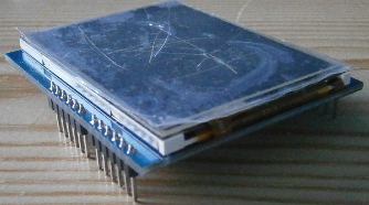
I have a iteadstudio 2.4 tft touch shield that currently works with my Arduino Uno R3 board.
I now want to get this shield working on the Arduino Mega 2560 R3 board.
first up this shield is a little old,
the manufactures does state that the board does work with the Arduino Mega
link http://imall.iteadstudio.com/development-platform/im120417012.html

this is the code from my sketch

#include <UTFT.h>
#include <UTouch.h>

// Uncomment the next two lines for the Arduino Mega

//This is my attemp in trying to initialize shield
UTFT myGLCD(ITDB24E_8, A5,A4,A3,A2); // Remember to change the model parameter to suit your display module!
UTouch myTouch( A1, 10, A0, 8, 9); // original values 6,5,4,3,2);

// Declare which fonts we will be using
extern uint8_t SmallFont[];
extern uint8_t BigFont[];

void setup(void)
{
/* Start Ethernet sheild */
Ethernet.begin( mac,ip,subnet,gateway );
delay( 100 );

/* Initalize LCD screen */
myGLCD.InitLCD( 1 );

/* Clear LCD Screen */
myGLCD.clrScr();

//myGLCD.setColor(0, 255, 0);
myGLCD.setBackColor( VGA_AQUA );
myGLCD.setFont( BigFont );

myTouch.InitTouch( 1 );
myTouch.setPrecision(PREC_HI);
drawLCD();
}

void loop(void)
{

if( myTouch.dataAvailable() )
{
myTouch.read();
x = myTouch.getX();
y = myTouch.getY();

if( ( y >= 15 ) && ( y <= 122 ) )
{
if( (x >= 2 ) && ( x <= 148 ) )
{
//waitForItTemp0(5,5,309,230);
//backButtonTemp0();
}
}

}

TftSheild6001.png

Have you managed to make it work with Mega? I'm trying to make the same shield work with DUE ... but cannot so far :frowning:

The librairies (TFTLCD and UTFT) are made so the pins used for data (D0 to D7) are not at the same place.
UNO LCD
8.............................LCD_D0
9.............................LCD_D1
2.............................LCD_D2
3.............................LCD_D3
4.............................LCD_D4
5.............................LCD_D5
6.............................LCD_D6
7.............................LCD_D7

MEGA LCD
22.............................LCD_D0
23.............................LCD_D1
24.............................LCD_D2
25.............................LCD_D3
26.............................LCD_D4
27.............................LCD_D5
28.............................LCD_D6
29.............................LCD_D7

You can wire 1 by 1 each pins between the MEGA and LCD (that's what I have done ;-). You can also edit the library for changing the pins. On the 2nd option, it will be very slow, because on MEGA, the pins 2 t 9 are mapped on many different processor ports, your code will take much more time to execute.

Hello,

I connected the pins in Mega 2560 to the corresponding LCD pins and RS-38,WR-39,CS-40,RST-41. But it still did not work. The screen just blinks as I set the timer, but not any color or display that I had set for it.

Is there any changes I need to do to UTFT?

Thanks.

berni_:
The librairies (TFTLCD and UTFT) are made so the pins used for data (D0 to D7) are not at the same place.
UNO LCD
8.............................LCD_D0
9.............................LCD_D1
2.............................LCD_D2
3.............................LCD_D3
4.............................LCD_D4
5.............................LCD_D5
6.............................LCD_D6
7.............................LCD_D7

MEGA LCD
22.............................LCD_D0
23.............................LCD_D1
24.............................LCD_D2
25.............................LCD_D3
26.............................LCD_D4
27.............................LCD_D5
28.............................LCD_D6
29.............................LCD_D7

You can wire 1 by 1 each pins between the MEGA and LCD (that's what I have done ;-). You can also edit the library for changing the pins. On the 2nd option, it will be very slow, because on MEGA, the pins 2 t 9 are mapped on many different processor ports, your code will take much more time to execute.

So, for us complete noobs, which wires have to go where? Perhaps you could post a picture or a schematic? Also, which file would I have to edit if I go with the second option?

Check my thread here [SOLVED] Cannot get ITDB02-2.8 to work with Arduino Mega 2560 (screen blank) - Displays - Arduino Forum for the solution to the problem.

Hope that helps!

The post you provide is for 2.8 " TFT shield. What I'm using is 2.4 " TFT shield. My screen doesn't display anything, either. I tried the method the post gave (uncomment line 7 "#define USE_UNO_SHIELD_ON_MEGA 1" in original UTFT library ), but it still doesn't work.

By the way, does the 2.8 " TFT shield have the same features and applications as the 2.4 " TFT shield have?

I would presume they have identical pinouts (cheaper to make that way), so what works for the 2.8" should work for the 2.4". They are exactly the same, except for the size.

Yeah, I actually checked the pinouts, they are completely identical. 2.4": ftp://imall.iteadstudio.com/IM120417012_Arduino_2.4eTFT_shield/DS_IM120417012_2.4eTFTTouchshield.pdf
2.8":
ftp://imall.iteadstudio.com/IM120417020_2.8_TFT_LCD_Touch_Shield/DS_IM120417020_2.8_TFT_LCD_Touch_Shield.pdf

What that means is that you have the pins right, most likely.

On a side note, as I was moving my keyboard, the cable got stuck in my chair so that it was too short, making me drop the keyboard onto my 2.8" LCD directly beneath it, breaking it. Now the touch part isn't working at all. Oh well, I had to laugh a bit at the one-in-a-million accident.