I have a small project I need some help with. I have never used any software to create a PCB for manufacture. i plan on learning how but for now I am under a time crunch. For this project I need to get about 12 to 16 small boards made. Could some one help me with a lay out? FYI I run Linux at home and have not picked out a fab house yet.
What I have in mind is about a 1" by 1.5" board that holds 2 max485 chips, termination resistors and a 12V to 5 V regulator. All threw hole for easy home soldering. This board would allow me to extend the output pins of the Arduino to distant displays via RS485.
Each board will be able to be configured as a send or receive at the time it is built via trace cut or solder bridge. I am also thinking a couple of extra holes to allow for mounting and maybe some add-on. I have a working schematic and I can talk further if any one is interested. Any files produced will be made open source.
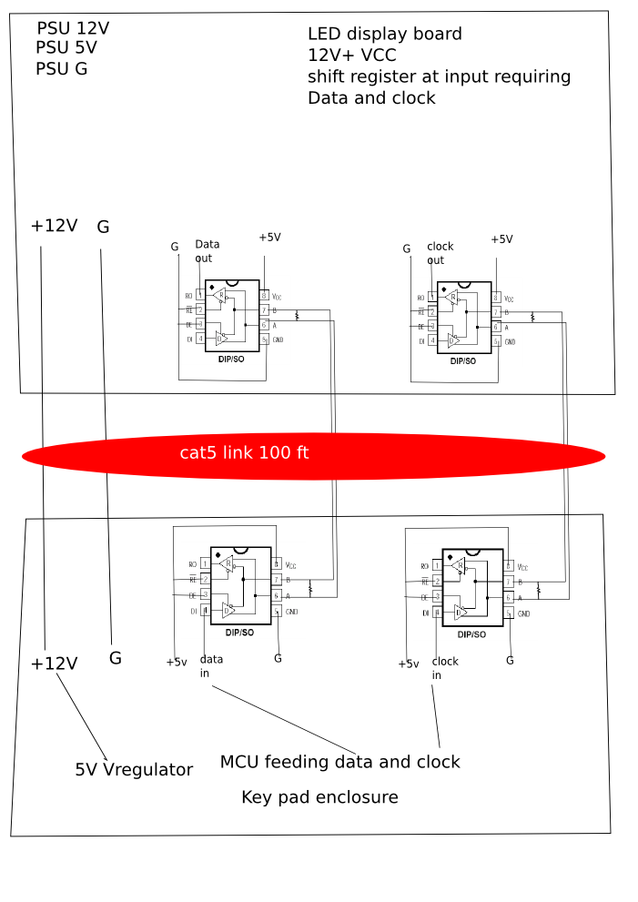
Here is the over all use for the board. I still need to test and draw up the voltage regulator part of it. I also need to finalize what I want to be optional. I am thinking I may have to draw it out.
So you can make a single board with a few jumpers to do both ends eh?
It's a small job but you probably need someone who uses Eagle so your files are easily exchangeable and able to be worked on by others.
That leaves me out
Alternatively the program that I think Crossroads uses (can't remember the name right now), it's free and you can upload directly to the fab house. You could probably learn enough for this job pretty quickly.
The easiest and cheapest route would be to go with Pad2Pad. Their software is far easier to learn than eagle, and their prices will be lower for so few boards. You'll want to learn Eagle eventually, but if you're in a time crunch you probably don't wanna mess with that.
Graynomad:
So you can make a single board with a few jumpers to do both ends eh?
Rob
Yes one board that can do each end. I also do some DMX stuff and this would work for that as well!
I got a 7805 5V regulator yesterday and wired it into the circuit. Works good. I will have to watch thermal management tho. I tried 1 regulator driving an arduino, 4 max485 and a small version of the display. With a little heat sink I was able to keep it fairly cool.
I think I am going to try a couple of the lay out programs and see what I can do.
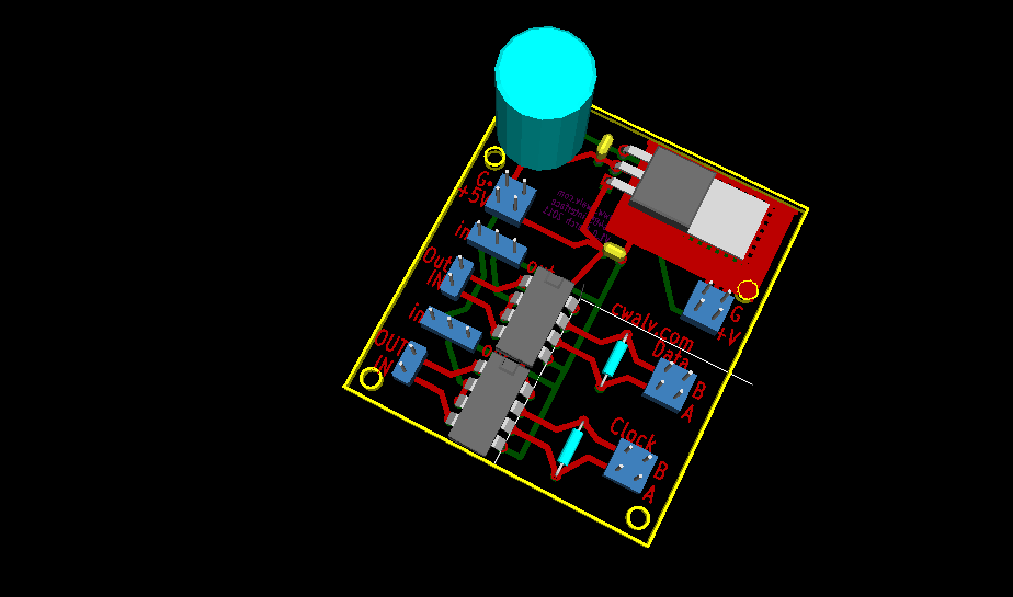
OK, I just hunkered down and did it in KiCad. Any one see any glaring problems? One concern I have is that the Vreg does not seam to have a full copper landing pad for heat dissipation.
The second file is a cad file, not sure what else I would have to do with it to get gerber files.
Here is a zip with gerber files and minor update to the .brd file.
Is this all I need to get the boards made? I added a hole for the v regulator mount. Was this even needed?
KE7GKP:
Unless you want to wait for another Linux/Kicad user to come along (good luck with that), you should probably post files that the other 98% of the world can view.
Instead of a smart a-- comment maybe it would be helpful to tell me what that is? Destructive criticism is pointless.
Sorry. I was more referring to file types a fab house would take. PNG and PDF are fine for a forum but pointless for figuring out if a fab house can take a file.
I do appreciate the schematic you made, tomorrow I will compare it to mine and make sure they agree on the key points.
As far as Linux VS Mac VS M$ is a moot point. As far as I can tell most if not all of the main PCB programs are cross platform in some fashion. This is an open source forum for geeks. The percentage of Linux users here is probably well above the norm.
KE7GKP:
While Graynomad is chewing his arm off, I threw together what I think would make a nice little universal RS485 3-channel driver/receiver board. The same board should work at each end. The solder bridges let you "hardwire" the channels for send or receive. And you can select several different power options for the send or receive ends. (Remember that 7805 is symmetrical and can be inserted in either direction depending on what you need.) I don't have time to do the board layout until tomorrow, but here is my proposed schematic.
out of total noobishness : what does this thing do anyways?
This board allows me to send some signals (in this case clock and data to an LED display) long distances and to multiple locations. I am also sending 12V power down the wire as well.
The IO pins on the Arduino and other logic chips are only made to drive signals a few inches on a circuit board. The max485 chip we are using here can take those signals and convert them to an RS485 hardware layer. RS485 is good for several thousand feet and driving 30+ slave units. You can read more about RS485 on wiki and a few other pages, it has been around for a VERY long time.
I also added a 5V regulator so I can power the max485 chips and some external devices I use that are 5V only. If you have any more questions just ask.
The layout looks good.
I think your 22uF cap model may be a little too big.
Compare that to this 100uF, 16V cap which can be seen to be about 0.15" wide, versus what looks like twice that.
Thank you. I am a little bit confused on the capacitor size.
The data sheet says .22uf for in and .1uf for out. However the normal values I see on line are 100uf in and 10uf out.
Here is an updated version that would let me use ether or both size capacitors.
I have looked at many manufacturs data sheets for 7805s, and all show 0.33uF on input & 0.1 on the outout.
Bigger will not hurt.
The physical size of the parts will vary.
I just finished making 12 boxes, half had 12V sourced over 40-50 foot cable. I used 1uF on the input and 0.47uF on the output, that's what I had on hand, worked just fine. Neither were physically big as the your model has. If the board can take a large part like that, than a smaller part would certainly fit.
tjbaudio:
This board allows me to send some signals (in this case clock and data to an LED display) long distances and to multiple locations. I am also sending 12V power down the wire as well.
The IO pins on the Arduino and other logic chips are only made to drive signals a few inches on a circuit board. The max485 chip we are using here can take those signals and convert them to an RS485 hardware layer. RS485 is good for several thousand feet and driving 30+ slave units. You can read more about RS485 on wiki and a few other pages, it has been around for a VERY long time.
I also added a 5V regulator so I can power the max485 chips and some external devices I use that are 5V only. If you have any more questions just ask.
ok but what's the practical use of it? Give me some example on what I can do with it?