I buyed a Dynament Premier Sensor, a very good infrared sensor to get % of co2 in a gas. To connect it to arduino I must add a MAX232 interface. I used a MAX3232 connected:
sensor tx: t1in
sensor rx: r1out
arduino tx: r1in
arduino rx: t1out
Sensor 3,3v from arduino
max3232 5 volt from arduino
but I receive nothing, if I disconnect sensor TX I receive something but from MAX232 (I thing) 0 and 255 values sparse.
There are differences between MAX3232 and MAX232?
attached the document to read from sensor.
I'm using standard SoftwareSerial.h to try to read.
Why did you power it with 3.3V, I think they can be used with 5V.
Are you sure that it uses RS232 levels ? Or is it using serial 5V TTL levels ?
Are you sure the sensor itself contains all the logic for serial communication ?
I think the document for communication protocol is for the OEM board.
The sensor itself seems to be analog.
I hope you didn't damage the sensor or the OEM board with high voltage levels from the MAX3232.
The MAX3232 is for 3.3V and 5V, and the older MAX232 is only for 5V.
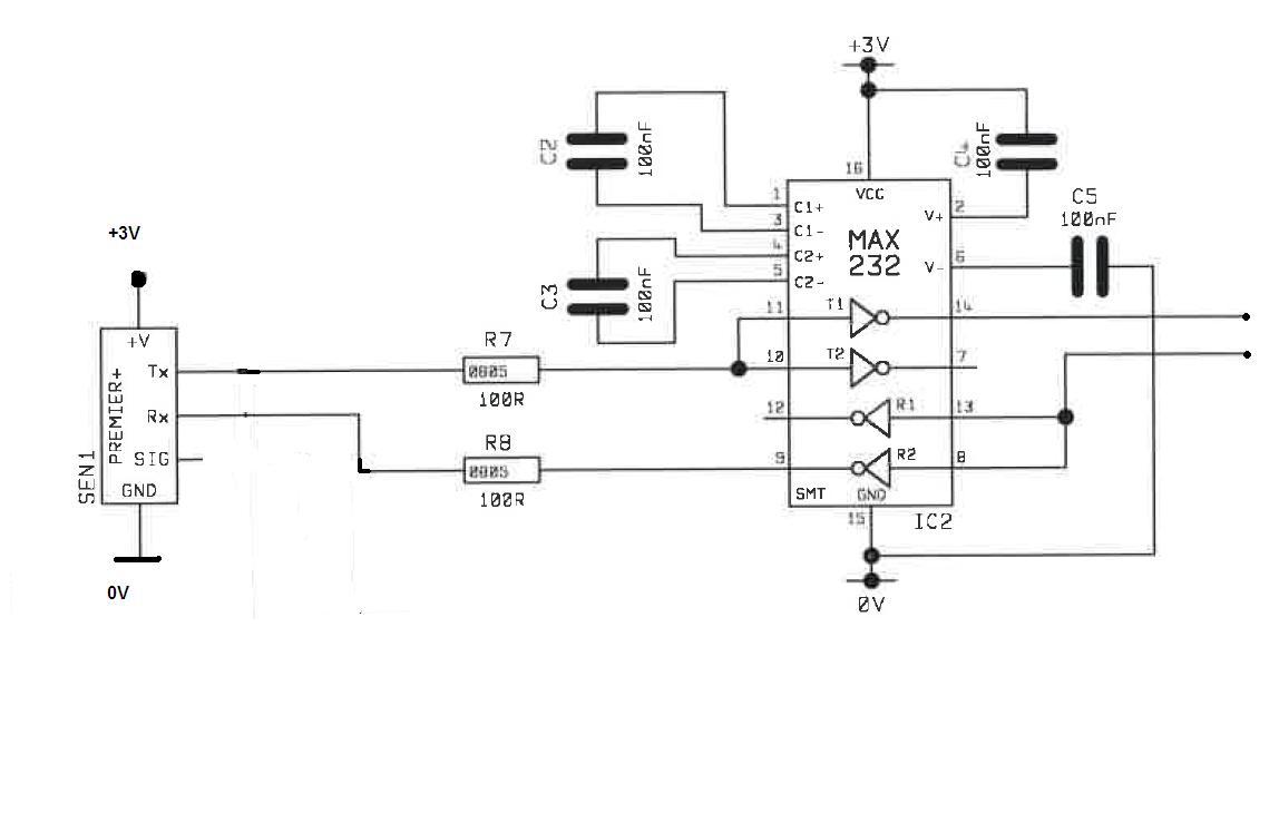
The staff of Dynament said me that sensor must communicate with max232 with this attached schema, I connected the 3,3v from Arduino.
what do you need? Some documentation? Did you see the attach with standard communication used by sensor?
he said me: "If you have RS232 input you need to invert the sensor towards max232. Please see attached diagram which actually is a working application. "
The schematic is to make RS232 high voltage levels, to be able to connect the sensor to the RS232 serial port of a PC.
You don't have to make your own MAX232 or MAX3232 circuit. If you search Ebay for "rs232 ttl" you will find many adapters to make TTL (5V) level serial signals. It's always good to have something like that, in case you want to connect the sensor to a PC.
Explanation: If you take a look of the datasheet of the MAX232, the pins 8,13,7,14 are the high level signals, and the 9,10,11,12 pins are the 5V TTL level pins. Now take a look at the schematic they gave you, and you see that the 5V TTL level signals are connected to the sensor.
To connect it to the Arduino, forget the MAX232. Use the 3.3V (perhaps 5V is possible), and connect sensor RX to a Arduino SoftwareSerial TX pin, and sensor TX to SoftwareSerial RX pin.
Hi all, I have a Dynament sensor and an Arduino Mega 2560. Am I safe if I plug the sensor this way and program the arduino to talk to the sensor using its TX1 and RX1? :