Illuminato board with 42 I/O's

Howdy and Happy New Year :slight_smile:

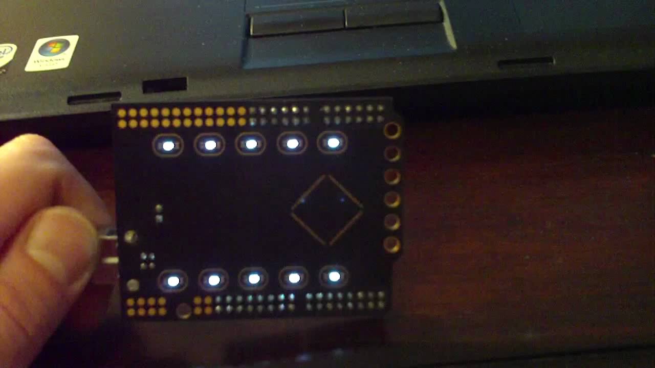
I just finished building the Illuminato board, and wanted to show some pictures and a video. I'd like to make it an official "Arduino" but for now it's a Freeduino or something like that. Anyway, it has 64k of code space and 42 digital I/O pins, since the idea was to make it run larger projects, like dual LED matrices, robots, or tons of sensors.

I tried really hard to keep it the same format as the original Arduino, so that all the shields people have made will snap on top of it, and work like they do on a normal board.

On the back side of the board are 10 white LED's that can be PWM'd or turned on or off with the bling() function (which I guess technically makes it a non-standard addition to the base function set).

Here's a video of the board controlling a dual-color LED screen directly:

And here's a video of the backlighted LED's pulsing :slight_smile:

Anyway, since it was built for an educational institution, and the professor that wanted it is funding it (so I could get volume pricing on a lot of the parts) the board is going to be $29.99 fully assembled, and if you really want a kit, just let me know and I can send you the parts. http://www.liquidware.com/shop/show/ILL/Illuminato

In the meantime, the schematics and code are here:

http://www.liquidware.com/wikipages/name/Illuminato

Let me know if you want a one-off board... like with built in op amps, or extra capacitors or something. The board files are GNU GPL'd, but I'm definitely happy to change or edit them for you, or walk through why I made certain things go where they did...

wow, that looks really cool. besides the technical parts i love the way you designed the pcb.

...beautiful

Very interesting.
Do you need to modify the IDE in any way, Or can you use it as is?

Gordon

in the video you mentioned the six holes are for programming the board? how does that work? with some sort of docking station?

Thanks a lot - I was going for the whole T-800 CPU chip look in Terminator 2 (the one they had in the glass case at Cyberdyne systems)... except I rotated everything 45 degrees off-center, and symmetrical. Whenever there was a part on one side of the board (like an LED resistor), I made sure to put it's counter-part on the other side. Also, I used hidden vias to keep the backside plane of the board "clean" looking... :slight_smile:

@bara.munchies - I didn't want to have in-circuit-programming pins sticking up from the board, since I've never personally used them in any of my projects, but they're still needed to actually program the chip with a bootloader the first time. So 4 of the 6 gold plated holes at the front of the board actually double as the ICP pins... and I use a couple of male header pins to program the bootloader - they fit right into the holes...

@GordonEndersby - The IDE needs a core folder that drops into the hardware/cores folder in the IDE folder, since it needs to map new names... but yeah, the same avr compiler works for this chip... I'm almost done porting some of the libraries, and I'll probably work with David Mellis to do the rest since I think he's doing it too for future Arduino's...

@AlphaBeta - I got the design ideas from Chris Ladden - he calls it circuit-based aesthetics. He gave a presentation up in Hartford that I attended, on treating a PCB like a painting. He has some pretty ridiculous tricks up his sleeves that he's used in board designs... I'm just a newbie compared to what he can do... but I'm catching up

Super awesome layout, very logical and backwards-compatible expansion with the way the I/O's are set up, nice choice of mask colors and gold plate, love the accent/underglow lights.

This is truly the Cadillac of Arduinos.

Thanks! :slight_smile: I literally spent hours looking through tons of designs (e.g. from Seeduino, old reprap and Make controller prototypes) until I settled on this layout.

I went from a few sketches and mockups (actually I really wanted to cut out a big hole in the middle of the board so you could snake wires up through it like the drawing on the left and the bottom):

To a 3-d "simulation" of the circuit - which helped me when placing the parts, so I knew approximately how it would look visually:

I left all of the writing and PCB ink off the board, because I didn't think it would look as nice with tons of letters everywhere. Plus it ended up being so small you could barely read it. But just so that I didn't forget the naming of the pins, I made this little cheat sheet (here's the bigger version - http://www.liquidware.com/wikifiles/23):

some of the details like the big holes could very well be parts of some geeky jewelery items. the gold and dark pcb have a nice contrast.

Yes it does look good .
Need a little mod for the people who use the xbee shield for that uses the icsp port.

inthebitz, I love your design. I'm gonna buy one, and put it on the wall :slight_smile:

It sure does look good. Had a quick around the site for the 'drop-in' files for the Arduino IDE.
Would appreciate if you point me to a link, I am curious to see how much (if any) modification will be required for libraries that directly access the i/o port registers and timers.

@peter247 - yep, me included. i've started playing around a lot more with my xbee shields, and noticed that they use the icsp port for just 5 and G, and since i use them on extendershields, i've had to wire them over anyway manually. i figured since i'm doing that anyway, why not? also, the "power bank" row is duplicated (the inner bank has another 5 and G), so i figured i'd just tap into there

@mem - not too bad, actually. yeah i'm still cleaning them up, and didn't want to confuse anyone by posting them before they were ready. i'll post them on the wiki now. in the meantime, the wiring.c file top part looks something like this:

PIN_DESC_T const pinTable[] = {

/* 0 / { &PORTE, 0, &PINE, &DDRE }, //PCINT0
/
1 / { &PORTE, 1, &PINE, &DDRE },
/
2 / { &PORTE, 2, &PINE, &DDRE },
/
3 / { &PORTE, 3, &PINE, &DDRE },
/
4 / { &PORTE, 4, &PINE, &DDRE },
/
5 / { &PORTE, 5, &PINE, &DDRE },
/
6 / { &PORTE, 6, &PINE, &DDRE },
/
7 */ { &PORTE, 7, &PINE, &DDRE },

/* 8 / { &PORTD, 2, &PIND, &DDRD },
/
9 / { &PORTD, 3, &PIND, &DDRD },
/
10 / { &PORTD, 4, &PIND, &DDRD },
/
11 / { &PORTD, 6, &PIND, &DDRD },
/
12 */ { &PORTD, 7, &PIND, &DDRD },

/* 13 */ { &PORTG, 0, &PING, &DDRG },

/* 14 / { &PORTB, 0, &PINB, &DDRB },
/
15 / { &PORTB, 4, &PINB, &DDRB },
/
16 / { &PORTB, 5, &PINB, &DDRB },
/
17 */ { &PORTB, 6, &PINB, &DDRB },

/* 18 / { &PORTG, 3, &PING, &DDRG },
/
19 */ { &PORTG, 4, &PING, &DDRG },

/* 20 / { &PORTD, 0, &PIND, &DDRD },
/
21 */ { &PORTD, 1, &PIND, &DDRD },

/* 22 */ { &PORTG, 1, &PING, &DDRG },

/* 23 / { &PORTC, 0, &PINC, &DDRC },
/
24 / { &PORTC, 1, &PINC, &DDRC },
/
25 / { &PORTC, 2, &PINC, &DDRC },
/
26 / { &PORTC, 3, &PINC, &DDRC },
/
27 / { &PORTC, 4, &PINC, &DDRC },
/
28 / { &PORTC, 5, &PINC, &DDRC },
/
29 / { &PORTC, 6, &PINC, &DDRC },
/
30 / { &PORTC, 7, &PINC, &DDRC },
/
31 / { &PORTG, 2, &PING, &DDRG },
/
32 / { &PORTA, 7, &PINA, &DDRA },
/
33 / { &PORTA, 6, &PINA, &DDRA },
/
34 / { &PORTA, 5, &PINA, &DDRA },
/
35 */ { &PORTA, 4, &PINA, &DDRA },

/* 36 / { &PORTF, 5, &PINF, &DDRF },
/
37 / { &PORTF, 4, &PINF, &DDRF },
/
38 / { &PORTF, 3, &PINF, &DDRF },
/
39 / { &PORTF, 2, &PINF, &DDRF },
/
40 / { &PORTF, 1, &PINF, &DDRF },
/
41 */ { &PORTF, 0, &PINF, &DDRF },

/* 42 */ { &PORTB, 7, &PINB, &DDRB },
};

@Peter - haha, thank you! me too, i think... on a black matte background, with the bling() function turned on... hmmmmm

@mem - ok, the core files are up here: http://www.liquidware.com/wikipages/name/Illuminato but i'm just posting them for you :slight_smile: i'm still changing some of the other files as i type this, so i'll probably upload it a couple times before they're really ready at the end of the week

Looks like times are moving fast with the Illuminato board.

At this stage the programming got to be easy with lots of support.
I will have to see how to get one to the u.k , But for Im a day 2 of the ardunio Im have problem using the pins and memory of that.

this looks really really cool. quick question: are pins 36-41 digital output or analog input at first?

how many pwm pins are there? which pins are they on the board?

I love the way you made the core files, thankyou for commenting everything!

I was just starting to rewrite the core files to make them more friendly and easier to extend for other chips, but after glancing at your files, I realized that you already did what I was trying to do, so when I start making my own arduino clones for my students, my base will be your files, not the originals :smiley:

I'll be around, bye!

(Greetings from Chile to everybody! and please excuse my non-native english :stuck_out_tongue: )

my base will be your files, not the originals

Um, do you understand what the change from LGPL 2.1 (existing arduino core) to GPL 3 (illuminato core) means?
According to my training, it won't be possible to legally have a closed source app/project based on the illuminato core. I don't know whether that's the intent here or not, but that's the way the lawyers think...

Hi,

Very nice board, congratulations!

Anyway, since it was built for an educational institution, and the professor that wanted it is funding it (so I could get volume pricing on a lot of the parts) the board is going to be $29.99 fully assembled, and if you really want a kit, just let me know and I can send you the parts. http://www.liquidware.com/shop/show/ILL/Illuminato

The price you mentioned in the first post is US$ 29.99, but on your website it says 'Final price: US$ 34.99'. Which is the correct price or is it maybe including shipping?

@darudude - thanks a lot, pins 36-41 are initially configured as analog input, to mirror the arduino's behavior. then, they shift over to digital if you call pinMode()... i think that's standard behavior, but it's definitely changeable in the core files to start up by default as digital?

@ninoscript - hello from chile, and good luck! if you want any help you can always email me (not that you'll need it, but just in case) ... i think i'm going to write up how i did it for some blog posts because a couple other people sent me messages too...

@westfw - hmmm i'm definitely not a lawyer and don't know the first thing when it comes to legal licensing... i figured gpl was the way to go. is lgpl more universally friendly? i'm absolutely hoping that anyone uses my files in the most open way possible... companies, institutions, individuals, etc.

@crashingdutchman - i know i know :frowning: it was supposed to be 29.99 but now i only have a few left... (i bought 50 pcbs, and 30 were for my friend, and i'd better keep a couple for debugging and code testing) i didn't think i'd sell any more than i had, to be honest. so i was hoping that by increasing the price a little, no one else would buy one until i built more, and then i could lower the price back to 29.99. mike probably could have put it as "out of stock" but just in case someone reeeeeeeally wants one, they could buy it for $5 ... ugh now i wish i had built more ... anyone want to throw in some money with me to build another 50 or 100?