Hello!
What is best way to power any device with super capacitor without blowing device?
A boost switching regulator with a low input voltage range and low losses?
How much power are you after?
This little guy doesn't need many external components and works well with Low ESR supercaps.
[Edit]
Sorry, forgot to paste in the link:
What makes you think you'll blow the device.
As far as your device is concerned, it doesn't care whether you power it from the national grid, super capacitor, battery or two wires stuck into a potato.
The ability of a power source to provide current has no bearing (or is it bareing) on a devices current demand. (OK the purists will argue that the source impedance will affect current delivery capability but that only applies if you are demanding more than the source is designed to deliver)
For us complete novices in electronics, could someone show a simple wiring diagram that uses one of these "super capacitors"? I have a simple design I'm working on (basically an Arduino and an LCD powered by a 5 volt wall wart) and wouldn't mind a low cost way to have it have a short window of power backup.
OK, so I have read quite a few other threads that discuss this and it appears that powering an Arduino with a super capacitor is not a great idea. It also looks like you can't just put in the capacitor, you need to add circuity to regulate the power coming out (maybe going in as well.) Anyway not a big deal for my project so unless I'm missing something I guess I'll abandon the idea.
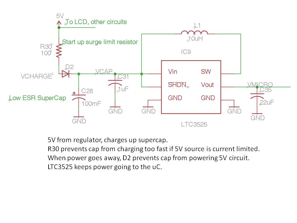
Did you look at the part in reply #2? Little 5-pin part, add a couple caps and an inductor. Not much too it.
Only 'hard' part is picking a low ESR cap at digikey.
I did look at the part but being a complete newbie I had no idea how to use it for this application. What you are saying is that you can use that under $2 part to "charge" the capacitor and to "regulate" the power coming out of it. I used the quotes because I'm not sure I'm using the correct terms. It does look like it is surface mounted which at this point I have not mastered either.
How long are you looking to stay up for? With the lcd backlight it may not last long
I had a 5.5v 1F cap and it lasted a barebones 328 about 3 minutes, with just one led indicator
It lasts my mega and the 328 with a few leds about 1 minute
so for short glitches or a nice smooth power supply it should work fine but other wise not reallly
also that time is when it shuts down, its not supposed to be run 16Mhz @<5volts , probably with glitches and unpredictable results, it quickly drops below 3.5 volts within 20 seconds
and maybe now is the time to master the smd? Its really not as hard as you think it is, atleast I found out its not so bad with a little practice
It's a novelty geek clock and I was thinking it would be nice if it didn't shut down with a momentary power dropout during a storm. It's not a high precision clock and I have already got too much in material costs into it to justify adding to much more in hardware or build time. I saw a note on another clock project:
http://www.etsy.com/listing/88340957/nixie-tube-clock-black-and-clear-acrylic?ref=&sref=
about it having a super capacitor (a .33F) and thought it would be a nice touch. I can see that the backup is for the time keeping circuit and not the entire clock display. My searching on how to implement this type of backup lead me here.
This video shows me powering an LOL shield for hours using an Ultracapacitor:

This video describes them:

My shield was still doing "something" 7 hours later:

BassnHarp:
I did look at the part but being a complete newbie I had no idea how to use it for this application. What you are saying is that you can use that under $2 part to "charge" the capacitor and to "regulate" the power coming out of it. I used the quotes because I'm not sure I'm using the correct terms. It does look like it is surface mounted which at this point I have not mastered either.
You can get small pre-built boards to do the boost to 5V (or 3V) so you don't have to mess with the parts. http://www.pololu.com/catalog/product/798 these have the same pin-out as a three-pin regulator so you can drop them in place.
I think what they are talking about is something like this:
http://ruggedcircuits.com/html/circuit__13.html
When the capacitor has charged it can power the circuit for a while, depending on its size.
However adding in the charge-pump gadget (not quite sure where that would go) you could use more of the capacitor's power. Say the capacitor starts at 5V, and starts discharging, the processor might cut out at 3V (say). But with the other gadget that boosts the capacitor's voltage back to 5V so it lasts until the capacitor has almost completely drained. Well that's the theory I think.
You know what, the fact that you use a Super Cap is not really an issue because as others stated it's going to pull the current it needs...
But, I use a 14.5v car battery charger which is connected to an SLA battery 7a/h , Now i have a voltage line going through a fuse into a Step Down voltage Regulator which can deliver 3 amps at 12v's quite nicely, it's perfect for Arduino boards..
But, be careful if you use the super cap to power other components on the breadboard, last thing you want to do is short out a super cap while wiring it up on the breadboard, 3amps is scary enough for a short, what about a super cap? discharge time faster than you can say "ouch i burnt myself"
Since this is to support a clock, another option is use a Real Time Clock chip with standard coin cell type battery backup.
http://www.dipmicro.com/store/DS1307N
http://www.dipmicro.com/store/BH2025
http://www.dipmicro.com/store/BAT-CR2025