Hi,
Im new to Arduino and electronics, Im doing a project for college using an arduino uno.
What Im trying to do is to automatically control a motor when light is sensed and when light is not sensed. So when light is sensed, the motor rotates forward and reverses when light is absent.
Im using an LRD to detect the presence of light. I have attached a diagram of my circuit. Im not sure if its right. I was able to turn on and off a led by covering/not covering the LDR. I have PIN 2 as a digital read. When I was monitoring this I noticed when the LED was on i.e light present, the monitor was reading a 0 and when the LED was off i.e no light, the monitor was reading a 1. I thought this should be the other way round?? I then wrote a digital output to PIN 3 and if the LED was on I wanted to write out 5v and if not I wanted to write out 0v. When I connected jumper from PIN 3 to the motor and motor to ground I got nothing however I am measuring 5vs across the PIN 3 lead and ground. Why am I not getting any rotation?? I have attached the circuit diagram and my code. Can anyone help??
thanks for the replies. I used the http://fritzing.org/ site to do up the circuit diagram. I thought because it was used on the arduino site that it would be recognised by other users.
Ok, so you have an LED with only 2 leads connected to +5, you've got both leads of the motor connected together apparantly shorting pin D2 to ground, some kind of transistor with its left lead connected to nothing, its middle lead connected to a resistor, and its right lead connected to ground. Luckily you had D2 set up as an input.
So, a couple of problems.
You are misusing the breadboard. The (in this orientation) columns of 5 pins are all connected together, so you did manage to get the transistor across three contacts - but not the motor. The upper 2 rows and lower 2 rows go all the way across the board, which you go right for ground but not for +5
An arduino pin is only good for 40mA, unlikely to drive anything but the very smallest of motors, and more likely to burn out the pin -especially when connected directly to ground. And then there is some thing in series with a resistor between +5 & Gnd.
If you're going to be designing more, I suggest downloading a simple to use schematic design tool like the one at expresspcb and create a real schematic. That fritzing is not real helpful when you're getting help from engineers.
In just a matter of minutes you can have a diagram like this that makes it clear what you are designing. Altho in this case fritzing did make it clear that you do not now know how to use the tools you have on hand yet, so I guess it can have some benefit.
Get yourself a multimeter also, and dowload Visual Analyser from http://www.sillanumsoft.org/ so you can have some basic oscilloscope functionality.
I assume you were going for something like this - not sure where you intended the LED to be - maybe driven by the transistor also?
Or driven in parallel with the base of the transistor?
"So when light is sensed, the motor rotates forward and reverses when light is absent."
To do that, you will need more transistors. Look up H-Bridge.
That uses transistors to flip the motor connections over - motor+ to+5 and motor- to ground, then motor- to +5 and motor+ to ground to have current flow the opposite direction.
beter use analog in and then you can set level of light/darkness - use "if" to determine light level tehn for simplest way use bipolar voltage source otherwise you should use double NO/NC relay (driven with mosfet) or H-bridge transistors
for this function you even arduino not necessary with potentiometer regulate light level to switch and if switching frequency/power is nat big you can use this schematic
I had been looking to download some freeware circuit simulation programs to test circuits. I found a couple. One called Yenga and another called Tina. Will the software you recommended be able to simulate circuits for me??
Yes I am using an LDR in the circuit. I have a basic electronics kit I bought and I had been building basic circuits from its manual. The breadboard in the kit is a little different so maybe I got confused when drawing the one using Fretzing.
I have attached a screen shot of the original circuit I built from the kit manual. This circuit lights up the LED in the presence of light and when you cover the LDR the LED goes off. What I tried to do was remove the battery source and use 5v power off the arduino. Then I used a jumper lead to connect to input PIN2. I placed the jumper lead between the LED and collector of transistor. I wanted the input to read if there was current flowing or not. As I said in my original post, when the LED was on, the input PIN was reading a 0 and when the LED was off it was reading a 1. Then I wanted output PIN 3 to power the motor.....
Maybe Im getting confused with this. The motor im using is small. Its a 3v motor as far as I know. If im measuring 5v across the output jumper from PIN 3 and ground how can this not power the motor?
expresspcb does not do simulation.
What will help more is a good schematic so you can see what you have - those cartoony drawings are not much good for debugging.
The atmega pin will put out 5v, but the transistor controlling it can only handle so much current before burning up.
Hi,
Im using a program called TINA 9 and it allows me to draw schematics and simulate them.
When you say the transistor will burn out, are you referring to the transistor on the breadboard or is there one on the arduino board?
As you can see my electronics knowledge isnt very good. Ive been working on this project for college and Im not getting very far!! I understand what the project is to do and I know theres inputs and outputs from the PIC, Im just having trouble doing up the circuit.
The basics of the project is a light activated door. i.e for a chicken coop.
When light is sensed (dawn), a phototransistor or LDR will be an input to the PIC. Two micro-switches will be used to detect if the door is opened or closed. i.e switch top and switch at bottom of door. These will be inputs to the PIC also. So if door is closed and light is sensed then output to an SSR relay to rotate motor forwards to open door. If light is not sensed and door is open then output to SSR2 relay to reversed motor to close door.
"transistor will burn out" -> the transistor that makes up the output driver of the ATMega - once it is fried, your output pin will not work, and possibly the whole ATMega chip may be ruined. If you feel it running really hot to the touch, that is usually what has happened.
Sensing the LDR and the switches, that part is simple.
Read up on H-bridges to control your motore, this article is a good start
Then come back with more details on the motor you are using and we can help you select components that can drive it.
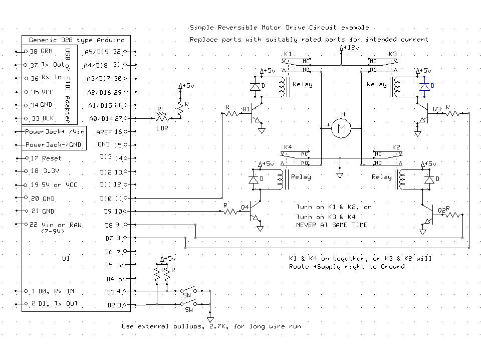
Here is a simple example using regular relays and drive transistors.
Thanks again for all the advice. I had a read up on the H-bridge and I have seen this before. It is used to reverse the polarity to the motor to allow bi-directional rotation.
I have attached the specs of the motor Im using. Circled in RED.
I think we need some more input from the group on how much current is needed to get that motor moving. I see 0.3A at maximum efficiency, can't tell what the stall current is, that's what your power suppply will have to source your drive circuit be capable of switching.